LoRa (Long Range) has become one of the most impactful wireless technologies for low-power, long-distance communication. It's not built for speed: it's built for reliability across kilometers, minimal energy use, and robustness against interference. Its low data rate and small packet size are optimized for short and occasional messages.
Unlike WiFi or Bluetooth, LoRa isn't meant for real-time streaming or large data transfers. Instead, it excels in applications such as: sensing network, distributed monitoring systems, long-distance signaling, …
To explore LoRa from a practical perspective, I built a long-range controller setup using Arduino ecosystem and a pair of LoRa modules. The goal was to keep things simple: press buttons on one device, and see the effect on the other device.
Why LoRa?
- Long range: up to several kilometers in an open field
- Low power: designed for battery-powered devices
- Small packets: perfect for commands, sensor values, and low-bandwidth data
- No infrastructure needed: devices communicate peer-to-peer
- High resilience: chirp spread spectrum (CSS) modulation handles noise and obstacles better than traditional radios
Project Overview
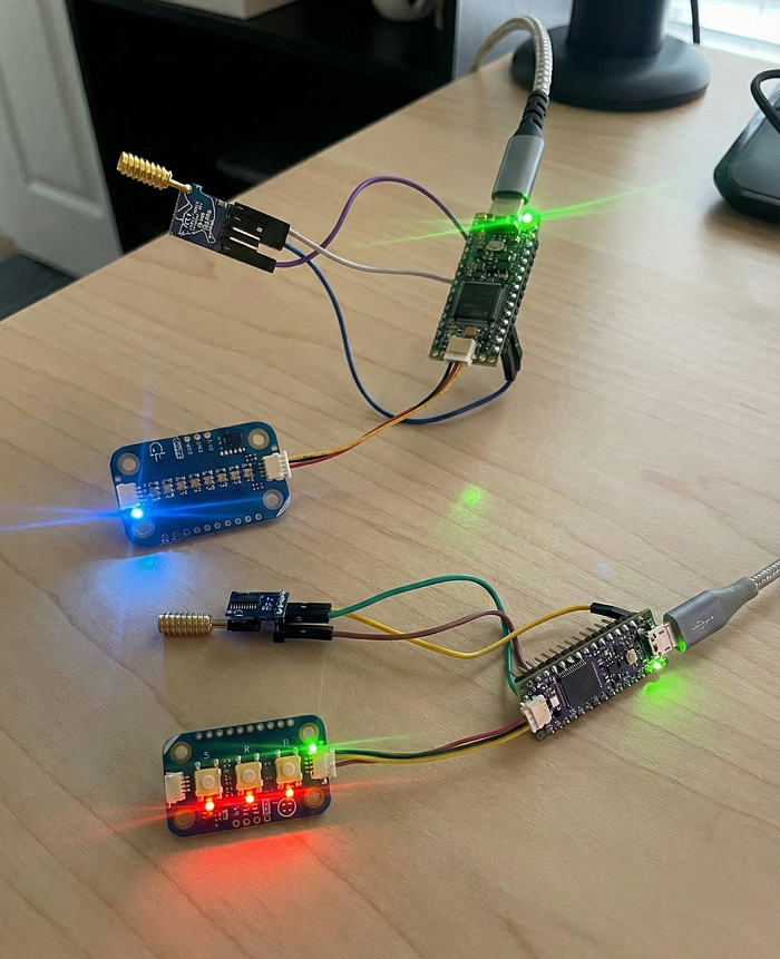
This project implements a simple long-range controller: one Arduino node sends LoRa commands when buttons are pressed, and a second node reacts by updating a LEDs bar.
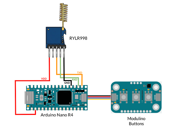
Transmitter
- Arduino Nano R4: the main microcontroller running the logic and handling serial communication with the LoRa module.
- Modulino Buttons: an I²C module with three buttons (A, B, C) used to trigger the LoRa commands.
- LoRa RYLR998 module: a LoRa radio module controlled via AT commands.
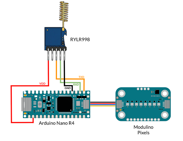
Receiver
- Arduino Nano R4
- Modulino Pixels: an I²C RGB LED module with 8 individually addressable LEDs used as the visual output.
- LoRa RYLR998 module
Schematics
The RYLR998 module connects via UART (D0-D1) to the Nano R4 using:
RYLR998-VDD <-> 3V3RYLR998-GND <-> GNDRYLR998-RXD <-> D0 (TX)RYLR998-TXD <-> D1 (RX)
Modulino modules use the dedicated QWIIC connector and cables.
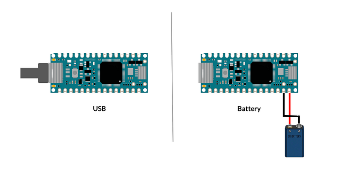
Both boards can be powered via USB or with a battery (for example, a 9V battery connected to the Vin and GND pins).
Controller Logic
The transmitter uses the buttons mapped to three LoRa commands:
- A → BRIGHT_UP
- B → COLOR_NEXT
- C → BRIGHT_DOWN
The receiver listens for incoming LoRa packets and updates a 8-LED pixel bar:
- BRIGHT_UP increases the number of illuminated pixels.
- BRIGHT_DOWN decreases it.
- COLOR_NEXT cycles through 5 preset colors: Red, Blue, Green, Violet, and White.
Message Format
Both nodes share the same simple command protocol:
BRIGHT_UP
BRIGHT_DOWN
COLOR_NEXT
No framing or checksums for this demo: just human-readable commands over serial. In a real application, it's better to include them to ensure reliable communication.
LoRa Setup
Each node needs a unique address for communication. In this demo:
- Transmitter node: address
1 - Receiver node: address
2
In the Nano R4, the
Serialobject is connected to the USB-C port for computer communication, whileSerial1is connected to pinsD0andD1for external device communication.
Example LoRa configuration in the transmitter setup():
// --- LoRa Setup ---
delay(200);
Serial1.println("AT+BAND=915000000");      // Set frequency band
delay(200);
Serial1.println("AT+PARAMETER=5,9,1,4");  // Set spreading factor, bandwidth, etc.
delay(200);
Serial1.println("AT+ADDRESS=1");          // Transmitter address
delay(200);
For detailed information about all available commands and parameters, see the RYLR998 datasheet.
Transmitter Logic (Nano R4 + Modulino Buttons)
The transmitter's job is extremely simple:
- Detect button events
- Send the corresponding LoRa command via
Serial1
if (buttons.isPressed('A')) {
  Serial1.println("AT+SEND=2,9,BRIGHT_UP");
}
else if (buttons.isPressed('B')) {
  Serial1.println("AT+SEND=2,10,COLOR_NEXT");
}
else if (buttons.isPressed('C')) {
  Serial1.println("AT+SEND=2,11,BRIGHT_DOWN");
}
Each message is sent using the RYLR998 AT+SEND=addr,len,data command, where:
2is the target addresslenparameter is the payload lengthdatais the actual command
Receiver Logic (Nano R4 + Modulino Pixels)
The receiver continuously monitors Serial1 for incoming lines.
When a full command is received, it updates the pixel bar:
- the bar can range from 0 to 8 LEDs
- color cycles through a predefined palette
Core reaction logic:
  if (msg.indexOf("BRIGHT_UP") != -1) {
    activePixels = constrain(activePixels + 1, 0, 8);
  }
  else if (msg.indexOf("BRIGHT_DOWN") != -1) {
    activePixels = constrain(activePixels - 1, 0, 8);
  }
  else if (msg.indexOf("COLOR_NEXT") != -1) {
    currentColorIndex = (currentColorIndex + 1) % 5;
  }
And the pixel bar update:
void updatePixels() {
  for (int i = 0; i < 8; i++) {
    if (i < activePixels) {
      pixels.set(i, *COLOR_LIST[currentColorIndex], 25);
    } else {
      pixels.set(i, OFF, 0);
    }
    pixels.show();
  }
}
What We Learnt
This project demonstrates how straightforward LoRa can be. You don't need complex stacks, gateways, or cloud services to experiment with long-range communication. A few lines of code, two modules, and a clear message protocol are enough to build an interactive LoRa system.
You can find the complete receiver and transceiver code here.