Most IoT tutorials start with everything going right. This one doesn't.
I burned an LCD and a relay in the same moment— wrong voltage, zero warning, instant regret. That single mistake rewrote the entire architecture of this project.
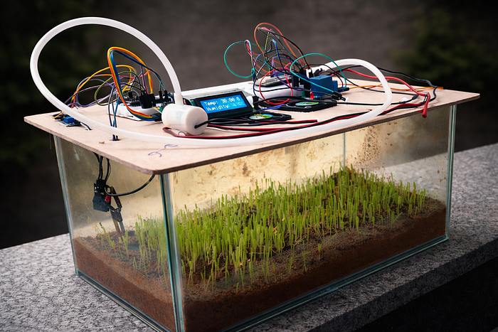
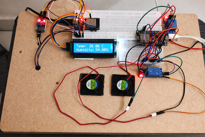
I wanted to see how far I could go with what I already had. No new components, no shopping list. Using an ESP32, an ESP8266, and Blynk IoT, I built a system that monitors temperature, humidity, and soil moisture in real time, and controls a water pump and fans, all from one app on my phone. Two boards, two power sources, one unified dashboard.
Working with what I had is also why things went wrong. And why the final design is more interesting than it would have been otherwise.
Everything I learned — including what not to do — is in this article.
How Does the ESP32 Know What Your Plant Needs?
One ESP32 handles everything on the monitoring side — reading data from sensors, displaying it live on a local LCD screen, and streaming it to the Blynk app over WiFi. Here's how each piece fits together.
ESP32 — Why This Microcontroller
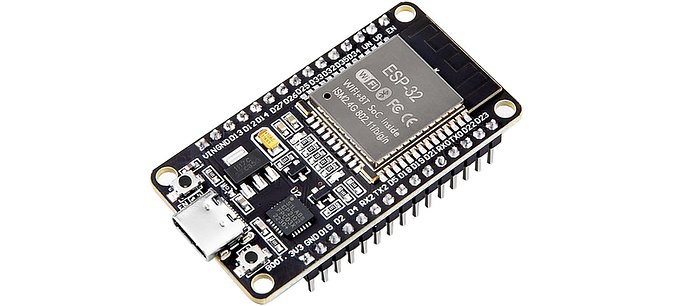
The ESP32 is the brain of the entire monitoring setup. It reads data from the sensors, processes the values, and drives the LCD display. The reason I went with the ESP32 over something like an Arduino Uno is straightforward — it has built-in WiFi which makes cloud connectivity effortless, and enough GPIO pins for all the sensors and peripherals I needed.
For environmental monitoring, the ESP32 works with two sensors — DHT11 for air conditions and a soil moisture sensor for what's happening underground
DHT11 Sensor:
I used a DHT11 sensor to measure temperature and humidity. It measures temperature from 0°C to 50°C (±2°C accuracy) and humidity from 20% to 80% (±5% accuracy).
Connection:
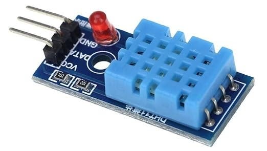
The DHT11 has three usable pins — VCC, Data, and GND. I connected the data pin to GPIO 4 on the ESP32. That's the only signal wire the sensor needs.
Code
The DHT11 code is split across three parts — and understanding why makes the whole sketch easier to follow.
First, we define the pin and create the sensor object globally, so the entire program knows about it:
#define DHTPIN 4            // Pin where the DHT11 is connected
#define DHTTYPE DHT11
DHT dht(DHTPIN, DHTTYPE);
DHT dht(DHTPIN, DHTTYPE) is where we create the actual sensor object — we're telling the code "there's a DHT11 on GPIO 4, I'm calling it dht." Without this line, the read commands later wouldn't know what sensor to talk to.
Inside setup(), we wake the sensor up once when the ESP32 powers on:
// Initialize the DHT sensor
dht.begin();
Serial.println("DHT sensor initialized.");
Then inside sendSensorData(), which runs every second, we ask the sensor for fresh values:
// Read temperature and humidity from DHT sensor
float temperature = dht.readTemperature();
float humidity = dht.readHumidity();
For simple prototypes, DHT11 works perfectly. If you need better accuracy, DHT22 is a direct upgrade with minimal code changes. For more advanced projects like IoT weather stations, the BME280 offers higher precision and additional atmospheric pressure data.
Soil Moisture Sensor:
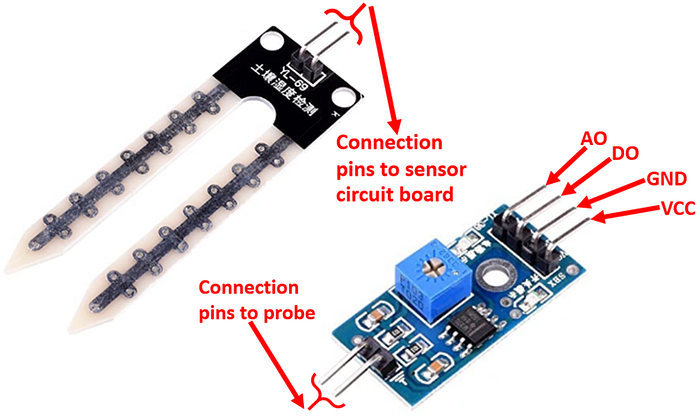
To measure soil moisture, I used a common resistive-type soil moisture sensor. It has two probes that measure electrical resistance between them — wet soil conducts better, so lower resistance means higher moisture. It gives both an analog output (a continuous value proportional to moisture level) and a digital output (HIGH or LOW based on a threshold you set with the onboard potentiometer). For this project I only used the analog output, so the potentiometer wasn't touched.
The sensor runs on 3.3V–5V and is widely used in smart gardening and irrigation systems. One honest downside: because it's resistive, the probes will corrode over time from continuous exposure to moist soil. For a short-term prototype it's fine — for a permanent installation, a capacitive sensor is the better choice.
Connection:
The sensor has four pins — VCC, GND, A0 (analog output), and D0 (digital output). Since we're working with continuous moisture values rather than a simple wet/dry signal, we connect the A0 pin to GPIO 32 on the ESP32.
Code:
First, we define the pin globally so the entire program knows where the sensor is connected:
#define SOILMOISTUREPIN 32 // Pin where the soil moisture sensor is connectedUnlike the DHT11, this sensor doesn't need a library or an object — analogRead() is a built-in Arduino function, so just defining the pin is enough. There's no initialization needed in setup() . The analog pin is ready to read the moment the ESP32 powers on.
Inside sendSensorData(), which runs every second, we read the raw value and convert it to a percentage:
// Read soil moisture level
int soilMoistureRaw = analogRead(SOILMOISTUREPIN);
// Map the raw value from 0-4095 to 0-100
int soilMoisture = map(soilMoistureRaw, 0, 4095, 0, 100);
The map() function scales the raw ADC range proportionally into a percentage. It's basically this simple formula: soilMoisture = (soilMoistureRaw / 4095) × 100.
For a long-term installation, swap this out for a capacitive soil moisture sensor. Same wiring, no corrosion issues.
Testing Your Sensors — Serial Monitor
Before adding the LCD or setting up Blynk, it's worth verifying that both sensors are reading correctly. The Serial Monitor is the simplest way to do this — it works completely independently of WiFi, Blynk, or the LCD.
Connect the ESP32 to your laptop via USB, open Serial Monitor in Arduino IDE, and set the baud rate to 115200 at the bottom right dropdown — matching the Serial.begin(115200) in the code. You'll immediately see live sensor readings printing every second:
// Print sensor data to serial monitor for debugging
Serial.print("Temperature: ");
Serial.print(temperature);
Serial.println(" C");
Serial.print("Humidity: ");
Serial.print(humidity);
Serial.println("%");
Serial.print("Soil Moisture (%): ");
Serial.println(soilMoisture);
If the values look correct here, you know your sensors are wired and working before touching anything else. This is a good habit for any hardware project — verify each layer before adding the next one.
Once the sensors check out, the next step is getting that data onto a local display.
Local Display — 16×2 LCD with I2C Module
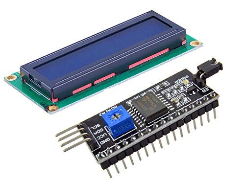
The 16×2 LCD gives a real-time local readout of all sensor values — temperature, humidity, and soil moisture. The I2C module on the back of the LCD is what makes this practical: instead of needing 6+ wires in parallel mode, I2C brings it down to just two data lines (SDA and SCL) plus power.
Connection:
The LCD communicates over I2C, which only needs two data lines —SDA to GPIO 21, and SCL to GPIO 22 on the ESP32. VCC goes to 5V, GND to ground.
Code:
In the code, the LCD address, columns and rows are defined as constants at the top:
#define LCD_ADDRESS 0x27  // I2C address of your LCD
#define LCD_COLUMNS 16
#define LCD_ROWS 2
LiquidCrystal_I2C lcd(LCD_ADDRESS, LCD_COLUMNS, LCD_ROWS);
The I2C pins are also defined globally & these are the ESP32's default I2C pins:
#define SDA_PIN 21  // GPIO pin for SDA
#define SCL_PIN 22  // GPIO pin for SCL
Inside setup(), Wire.begin() initializes the I2C bus,lcd.init() starts the display, and lcd.backlight() turns the backlight on:
// Initialize the I2C communication
Wire.begin();
Serial.println("I2C communication initialized.");

// Initialize the LCD display
lcd.init();
lcd.backlight();
Serial.println("LCD display initialized.");
Notice the Serial.println() after each initialization — these print to the Serial Monitor and tell you exactly which component initialized successfully. Really useful if something isn't working on startup.
Inside sendSensorData(), the display updates every second:
// Update LCD display with sensor data
lcd.clear();
lcd.setCursor(0, 0);
lcd.print("Temp: ");
lcd.print(temperature);
lcd.print(" C");
lcd.setCursor(0, 1);
lcd.print("Humidity: ");
lcd.print(humidity);
lcd.print("%");
lcd.setCursor(0, 2);
lcd.print("Soil Moisture: ");
lcd.print(soilMoisture);
lcd.print("%");
lcd.clear() wipes the previous values before writing fresh ones. Since the LCD only has 2 rows but we have 3 values to display, the screen naturally cycles every second — showing Temp & Humidity, then Humidity & Soil Moisture, then Soil Moisture & Temp, and back again.
The LCD shows data locally. Blynk takes it to your phone — from anywhere.
WiFi & Cloud — Connecting to Blynk IoT app
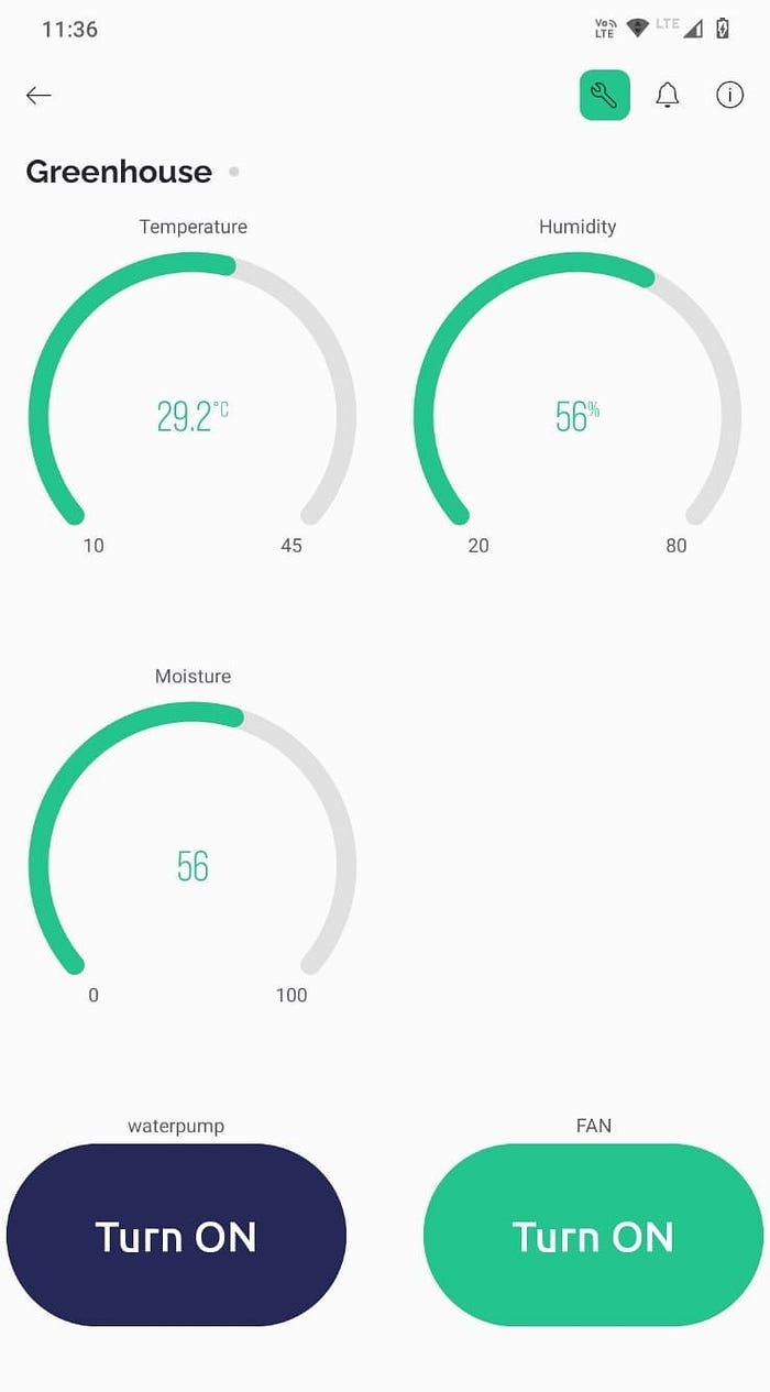
This is where the project goes from a local gadget to a remote monitoring system. Sensor data streaming live to your phone over WiFi. The credentials — SSID and password — are defined in the code. Once connected, Blynk.begin() authenticates the device with the Blynk Cloud using a unique Auth Token tied to your project template. After that, the device is live and data flows in both directions.
The Blynk dashboard has three gauge widgets — one each for temperature, humidity, and soil moisture — each mapped to a virtual pin (V0, V1, V2). The ESP32 writes sensor values to those pins every second.
Code
The Blynk template details, auth token and WiFi credentials are defined at the top:
#define BLYNK_TEMPLATE_ID "xxxxxxxxxx"
#define BLYNK_TEMPLATE_NAME "xxxxxxxxxx"

char auth[] = "your_auth_token";   // Blynk Auth Token
char ssid[] = "your_wifi_ssid";    // Your WiFi SSID
char pass[] = "your_wifi_password"; // Your WiFi Password
Inside setup(), Blynk.begin() connects to WiFi and authenticates with the Blynk cloud in one single call. The timer is then set to call sendSensorData() every 1000ms:
// Connect to Wi-Fi
Blynk.begin(auth, ssid, pass);
Serial.println("Connected to Wi-Fi.");

// Setup a timer to periodically update sensor readings
timer.setInterval(1000L, sendSensorData);
Serial.println("Timer interval set.");
The loop() stays completely clean — Blynk and the timer handle everything:
void loop() {
  // Run Blynk functions
  Blynk.run();
  // Run BlynkTimer functions
  timer.run();
}
Never use
delay()in a Blynk project — it blocksBlynk.run()and will disconnect you from the cloud. Always use BlynkTimer for anything time-based.
At the end of sendSensorData(), the three sensor values are pushed to their respective virtual pins on the Blynk dashboard:
// Send sensor data to Blynk app
Blynk.virtualWrite(V0, temperature);
Blynk.virtualWrite(V1, humidity);
Blynk.virtualWrite(V2, soilMoisture);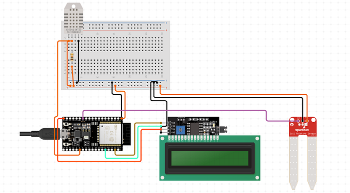
The full monitoring code is available on GitHub
One Board Wasn't Enough
I wanted to add two mini fans and a water pump that I could switch on and off directly from the Blynk app. The plan seemed simple — just add them to the same ESP32 that was already handling the sensors. The GPIO pins were more than enough. That wasn't the problem. The problem was power.
The Problem with One Board
When you connect sensors and actuators to the same microcontroller, they all draw current from the same source. The sensors were already using what the ESP32 could comfortably supply. When I tried adding the fans and motor to the same board, the actuators simply weren't getting enough current to run properly. The microcontroller just couldn't handle all of them at once.
The proper fix would have been an op-amp — an operational amplifier — which is an IC that can amplify the voltage to drive higher load devices. But I didn't have one.
So I tried something else — power the sensors from the ESP32, and power the actuators directly from a 12V external adapter. The microcontroller handles signals only, not the heavy lifting. I connected it directly to the LCD display and to the water pump through a relay. I hadn't connected the fans yet — luckily.
But the LCD and the relay didn't survive. The 12V was way too much for components rated at 3.3V–5V — they were gone.
That moment made the problem very clear: if you're powering through the microcontroller, you need to step the voltage up for higher load devices. If you're powering directly from an external source, you need to step the voltage down before it reaches the components. I had neither — no boost converter, no voltage regulator, no op-amp.
The Solution — A Separate Control Board
I decided to build a completely separate hardware system for control. Same Blynk project, same WiFi credentials, same app — but a different microcontroller handling only the actuators.
I already had an ESP8266. Like the ESP32, it has built-in WiFi, which meant it could connect to the same Blynk project and appear on the same dashboard. The ESP32 handles monitoring, the ESP8266 handles control. Two independent boards, two separate power connections, one unified app.
The Actuators
The control system drives two types of actuators — a 3V mini water pump and two 5V mini fans. The water pump is connected through Relay 1 and controlled by the water pump button on Blynk (V3). Both fans are connected through Relay 2 in parallel — one button on Blynk (V4) turns them both on or off at the same time.
The relays act as electrically controlled switches. The ESP8266 sends a signal to the relay, and the relay handles the actual switching load — so the ESP8266 never directly drives the actuators, it just tells the relay what to do.
ESP8266 — Why This Board
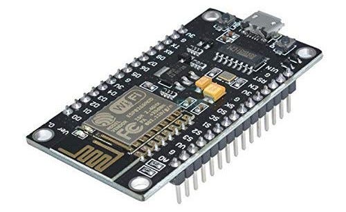
The ESP8266 is a step down from the ESP32 in terms of GPIO pins and processing power, but for this use case it's perfect — we only need two output pins and a WiFi connection. It's also cheaper and smaller, which makes it a good fit for a dedicated control board.
The key thing that makes this whole dual-board setup work is that both boards use the same Blynk template ID and the same auth token. So even though they are completely separate hardware systems with separate power connections, they both talk to the same Blynk cloud project and show up on the same dashboard. The gauges come from the ESP32, the buttons control the ESP8266 — the user sees it all as one unified interface.
Code
Just like the monitoring section, the control system code is split across the same three logical parts — and a new part unique to Blynk: the BLYNK_WRITE() handlers.
Defining pins and state variables globally:
The two output pins are defined at the top, along with Boolean variables to track whether each actuator is currently on or off:
#define WATER_PUMP_PIN D1  // Pin to control water pump
#define FAN_PIN D2          // Pin to control fan

bool isWaterPumpOn = false;
bool isFanOn = false;
The Boolean variables are important — they store the current state of each actuator, so the outputs() function always knows what to do every second.
WiFi and Blynk credentials:
Notice the template ID and auth token are identical to the monitoring sketch — this is what ties both boards to the same Blynk project:
#define BLYNK_TEMPLATE_ID "xxxxxxxxxxxxx"
#define BLYNK_TEMPLATE_NAME "xxxxxxxx"

char auth[] = "your_auth_token";    // Blynk Auth Token
char ssid[] = "your_wifi_ssid";     // Your WiFi SSID
char pass[] = "your_wifi_password"; // Your WiFi Password
Inside setup():
The output pins are initialized, and the timer is set to call outputs() every second:
// Initialize the serial communication
Serial.begin(115200);
Serial.println("Serial communication initialized.");

// Connect to Wi-Fi
Blynk.begin(auth, ssid, pass);
Serial.println("Connected to Wi-Fi.");

// Setup pins for water pump and fan
pinMode(WATER_PUMP_PIN, OUTPUT);
pinMode(FAN_PIN, OUTPUT);
Serial.println("Water pump and fan pins initialized.");

timer.setInterval(1000L, outputs);
Serial.println("Timer interval set.");
The outputs() function — runs every second:
This function checks the current state of each boolean and drives the pins accordingly:
void outputs() {
  // Control water pump and fan based on Blynk app commands
  if (isWaterPumpOn) {
    digitalWrite(WATER_PUMP_PIN, HIGH);
    Serial.println("pump is on");
  } else {
    digitalWrite(WATER_PUMP_PIN, LOW);
    Serial.println("pump is off");
  }

  if (isFanOn) {
    digitalWrite(FAN_PIN, HIGH);
    Serial.println("fan is on");
  } else {
    digitalWrite(FAN_PIN, LOW);
    Serial.println("fan is OFF");
  }
}
The BLYNK_WRITE() handlers — the new part:
This is what's unique to the control system. BLYNK_WRITE() is a special Blynk function that fires instantly the moment you press a button on the app. V3 handles the water pump button, V4 handles the fan button:
BLYNK_WRITE(V3) {
  int waterPumpState = param.asInt();
  if (waterPumpState == 1) {
    isWaterPumpOn = true;
    digitalWrite(WATER_PUMP_PIN, HIGH); // Turn on water pump
  } else {
    isWaterPumpOn = false;
    digitalWrite(WATER_PUMP_PIN, LOW);  // Turn off water pump
  }
}

BLYNK_WRITE(V4) {
  int fanState = param.asInt();
  if (fanState == 1) {
    isFanOn = true;
    digitalWrite(FAN_PIN, HIGH); // Turn on fan
  } else {
    isFanOn = false;
    digitalWrite(FAN_PIN, LOW);  // Turn off fan
  }
}
When you press "Turn ON" for the water pump on the Blynk app, BLYNK_WRITE(V3) fires immediately, sets isWaterPumpOn = true, and turns the pin HIGH. The outputs() function then keeps it that state every second until you press the button again to turn it off.
The loop() stays clean — same as the monitoring sketch:
void loop() {
  // Run Blynk functions
  Blynk.run();
  // Run BlynkTimer functions
  timer.run();
}
The full control code is available on GitHub. The key logic is already broken down in the snippets above
A Note on the Voltage Drop
During testing, I turned on both fans and the water pump simultaneously and noticed — the fans were spinning slightly slower compared to when the pump was off. This is a minor voltage drop caused by increased current demand when all actuators run together from the same power source. For a prototype it's completely acceptable, but for a production build a dedicated power supply for each actuator would eliminate this.
What Constraints Actually Build
Power management is harder than programming. You can debug code for hours and nothing breaks permanently. One wrong voltage assumption and two components are gone in a second — no warning, no recovery.
Constraints didn't just shape this project. They were the project. No op-amp meant a second board. A second board meant a second power source. A second power source meant a more resilient architecture than I would have ever designed on purpose. The mess produced something cleaner than the plan would have.
I'm not going to pretend that's always how it works. Sometimes constraints just produce a worse solution. But this time, the limitation forced a separation of concerns — monitoring on one board, control on another — that actually makes the system easier to debug and expand.
The next addition could be an LDR sensor for light intensity and a UV light strip — same dashboard, same constraint, same approach.
If you enjoyed this story, drop a comment below. If you want to see more stories, use the "Follow" or "Subscribe" buttons, and you will get a notification when the next article is published. The full source code for this article is available on my GitHub— your support may help me to get more hardware for testing and to write more articles like this.
Thanks for reading.