To transmit text or data using LoRa (Long Range) technology, you typically use a microcontroller such as the ESP32 and a LoRa module connected to the processor via the SPI interface. Additionally, you will, of course, need to write a program that sends or receives and displays the data. In this tutorial I will show you how to avoid all these inconveniences and quickly and easily perform LoRa transmissions with a LoRa module with a UART (Serial) interface.
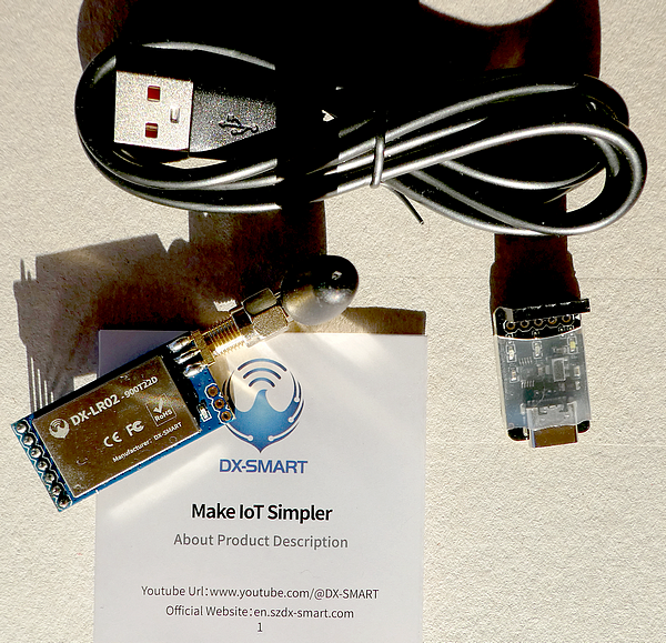
I recently ordered a set of two of these LoRa modules from AliExpress: DX Smart DX-LR02-T900D22S with USB-to-serial adapter, antennas, and USB cables. As I'm located in Germany/Europe, I'm using the variant that is operating in the 868 MHz LoRa frequency band.
Topics of this tutorial:
- profile of the LoRa modules
- support material from the manufacturer
- Software for the UART interface (Windows and macOS)
- Prepare the LoRa modules for your first test
- Commissioning and settings
- Practical use of the LoRa modules
- Simple range test
- Summary
Profile of the LoRa modules
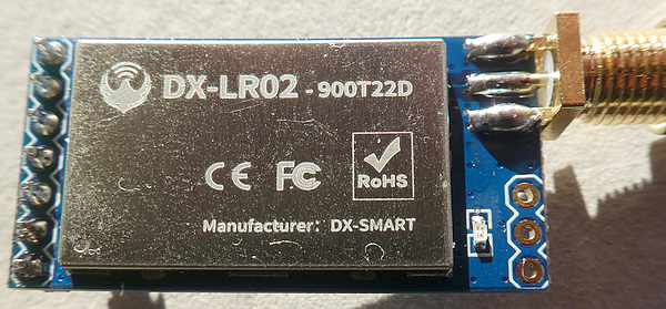
The LoRa modules are designed and distributed by the Chinese company DX-Smart Technology Co., Ltd. They are part of a series of LoRa modules for various applications. Interestingly, there is no entry for the model DX-LR02–900T22D on the website.
The modules contain the LR02 LoRa module, which is powered by an ASR6601 chip. The maximum transmit power is specified as +22 dBm, and the maximum range (with a clear line of sight) can be 5 kilometers. The sensitivity of the LoRa module is a good -138 dBm.
The module supports three operating modes: transparent transmission, fixed point-to-point transmission, and broadcast transmission. The control is achieved via (text-based) AT commands, which are transmitted from a computer to the module via the UART interface.
Finally, the module requires an operating voltage of 3.3–5 volts. I bought the complete two-piece package of LoRa modules, antennas, USB-to-serial adapters, and USB-C cables for around 14 euros, including shipping costs.
Support material from the manufacturer
Under the heading Support/Data Download, however, we can download additional material about our LoRa module, depending on your frequency band (868/915 MHz or 433 MHz). You can download a support package from a Google Drive folder. I'm recommending downloading the complete folder, and the most important document is in the subfolder 03-Technical Information.
Software for the UART interface (Windows and macOS)
The support package (see before) includes a Windows program that can be used without installation (UartAssist.exe) and is working properly. On my macOS, I'm using Serial Console Pro by Miroslav Petrov. The "Releases" section contains ready-to-use, pre-compiled Windows and macOS versions of the terminal program.
As the UartAssist Windows program is a little bit more user-friendly, I'm using this program for demonstration.
If you already programmed with ESP32 boards, you have probably installed the CH34x driver on your Windows computer before. A suitable driver is available in the support package (the Google Drive link includes UartAssist.exe and the CH34x driver; see subfolder 04-PC Test Tools). If you prefer to download a more recent CH34x driver, here is a link to the manufacturer's website (please use Google Chrome translator to get an English translation).
Prepare the LoRa modules for your first test
You might be thinking, "What do I really need to consider when putting this module into operation?" but a defective device won't help you either. The most important advice is:
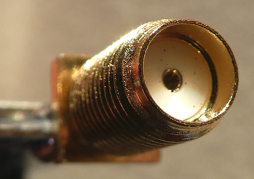
Never use the LoRa module without a connected antenna.
This is because with the default (fabric) settings, the device is transmitting with the maximum power of +22 dBm, and the (even unintentional) sending of data can irreparably destroy the device upon first use.
The second most important piece of advice is to check the transmission frequency and other technical settings when using it for the first time.
Commissioning and settings
There are just two connections that have to be made:
- Connect your computer with the USB-to-serial adapter module that comes with the module. A white LED is lighting, indicating power supply. There is a plastic shield to protect against any unwanted connections (I never saw this for a "low price adapter" :-)
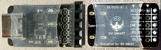
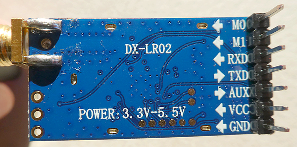
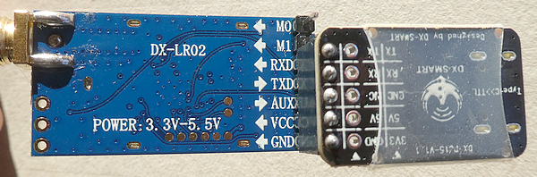
- Connect the 5-terminal female connector of the USB adapter with the 7 male pin connector as follows:
LoRA module - USB adapter
M0  - not connected
M1  - not connected
RXD - TX pin
TXD - RX pin
AUX - AUS pin
VCC - 5V pin
GND - GND pin
This is how the connection looks, and again, don't forget to connect the antenna before any wiring:
After connection, the red LED on the LoRa module is slowly blinking (but does not indicate any incoming or outgoing packets or module status).
Settings
As every LoRa connection needs at minimum one transmitter and one receiver, both (or all) devices need to use the same parameter settings. In my ESP32 LoRa projects, I made these settings directly in the software.
However, these UART modules require a different approach, namely manual operation via the UART terminal. Fortunately, these LoRa modules remember their settings, so I only need to configure them once at the beginning, but for each individual module.
For this tutorial, I'm using these settings to be compatible with my ESP32 LoRa project:
- Frequency: 863.500 MHz
- Spreading Factor: SF7 (fastest mode)
- Coding Rate: 4/5
- Bandwidth: 125 KHz
- Transmission power: 0 dBm (optionally, the lowest possible power with this module, as I'm transmitting very frequently during my tests and I don't want to disturb other devices nearby).
- Mode: Transparent mode (transmission is visible by all devices)
Now let's see how we can configure these settings in the LoRa modules. Please download the technical documentation (see "Support material from the manufacturer") and open the PDF file "DX-LR02–900T22D Serial port application guide.pdf", as it gives us the necessary information about the commands. As mentioned before, I'm using the Windows software UartAssist.exe for the screenshots.
After starting the software, we need to make some settings for the connection:
In Serial Options, use:
Baudrate: 9600 (UART Speed)
Databits: 8
Stopbits: 1
Paritybits: NONE
Flowctrl:   NONE

In Recv Options use:
Encoder: ASCII
Autolinefeed enabled

In Send Options, use:
Encoder: ASCII
select "Append Frame Tail":
  Append checksum: NONE
  Append frame tail CR+LF (gives 0D 0A)
  click on OK

Note: in older versions of UartAssist you select
"Auto Append Bytes", Algorithm: NONE, Frame Terminator
is 0D 0A, click on OK
If you made all the settings, click on the "Open" button, and the software connects to the module through the USB connection. The next steps are a rough summary of a YouTube tutorial (LR01/LR02/LR03 series product communication mode tutorial demonstration) that explains how to use these LoRa modules for all transmission modes.
The main window is divided into an upper and a bottom part. The upper part is the receiver window; in the bottom window, you type in your commands. As we are typing commands, the transmitter and receiver encoder should be ASCII.
Please enter "+++" (without the brackets) and press the "Send" button, and in the receiver window the module answers with "Entry AT". Now we are in the "command mode" that is required when changing or querying the settings.
Now enter "AT+HELP" to get a summary of the (default) settings:
>AT+HELP

===================================
LoRa Parameter:
+VERSION=V2.3.1
MODE:0
LEVEL:0 >> 244.140625bps
SLEEP:2
Frequency:868000000hz >> 24
MAC:ff,ff
Bandwidth:0
Spreading Factor:12
Coding rate:2
CRC:0(false)
Preamble:8
IQ:0(false)
Power:22dBm
===================================
In the following steps I'm using the commands described in the Serial port application guide with a <page number> for a look-up there.
Set Frequency:
Unfortunately, you cannot enter the desired frequency directly, and you have to choose a channel instead. The table on <pages 22 + 23> gives you an overview; please note that the channel numbers are in HEX encoding and in steps of 500 KHz, so you cannot use the (possible) frequencies in between them. The channel number for 863.500 MHz is "1B":
>AT+CHANNEL1B

+CHANNEL=1b
OK
Set Spreading Factor:
The parameter <page 25> for Spreading Factor SF7 is "7":
>AT+SF7

+SF=7
OK
B.t.w., this changes the Level value (see <pages 20 + 21>).
Set Coding Rate:
The parameter <page 25> for Coding Rate 4/5 is "1":
>AT+CR1

OK
Set Bandwidth:
The parameter <page 24> for Bandwidth 125 KHz is "0", but this is the default value, and these devices usually just have this option. The good news is we don't have to make a change in the settings with fabric settings.
>AT+BW0

+BW=0
OK
Set Transmission power:
This step is optional, but as we are going to send more than the allowed 1% airtime, it might be a good decision to reduce the transmission power to the lowest possible value to minimize the effect (disturbing) on other LoRa devices nearby. See <page 24> for minimum and maximum values; for a 0 dBm transmission power, we need the parameter "0":
>AT+POWE0

OK
Set Transmission mode:
To be compatible with my other ESP32 LoRa projects, we need to use the transparent transmission mode. This means that a transmission is visible for all other devices operating on the same channel (frequency), spreading factor, and coding rate. For more information about the different modes, please see the guide <page 18>. The parameter for "Transparent mode" is "0" (this is the default setting, but in case you had the mode before, here is the way to get this setting):
>AT+MODE0
+MODE=0
OK
Error conditions:
If you selected a wrong parameter or entered a wrong command, there are two error codes: "101" ("Abnormal parameter data") and "102" ("Instruction error"). After an error condition, the module stays in the "Command mode" and you can proceed as you wish:
Example for a wrong parameter (value 0 ist allowed only):
>AT+BW1

ERROR=101
Final check:
After all settings, we query the new parameters and exit the "Command mode" by sending a "+++" sequence:
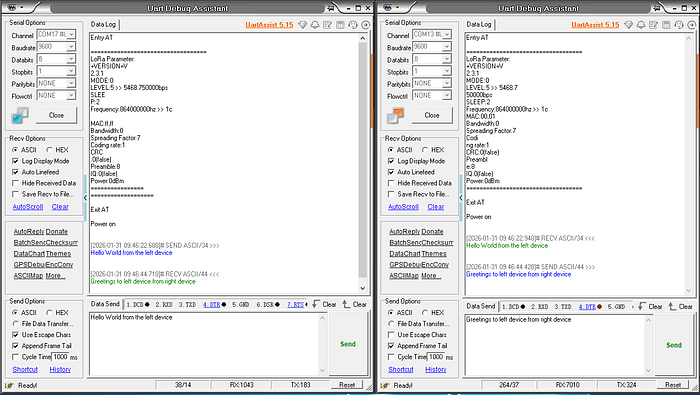
>AT+HELP

===================================
LoRa Parameter:
+VERSION=V2.3.1
MODE:0
LEVEL:5 >> 5468.750000bps
SLEEP:2
Frequency:863500000hz >> 1b
MAC:00,01
Bandwidth:0
Spreading Factor:7
Coding rate:1
CRC:0(false)
Preamble:8
IQ:0(false)
Power:0dBm
===================================
Exit the Command mode:
>+++

Exit AT
Power on
Note: Even if your LoRa module is in "Command mode", it will still receive incoming LoRa packets that match the current settings.
Practical use of the LoRa modules
As long as you are using an ASCII-encoded data transfer, you won't send binary-encoded data (e.g., the temperature is encoded in 4 bytes, representing a float value). In the end, the use case is to transfer short text messages over long distances between two devices. As both computers usually have a keyboard and display, it is super easy to type in the message and read the transmitted message on the receiver side.
In this tutorial I only use the "transparent mode", for the use of the other two modes, I refer to the support material and the YouTube link.
For this scenario, I started the UartAssist.exe two times on the same computer, connected both LoRa modules with different USB ports, and made some screenshots of both windows beneath each other.
If you are going to change the encoding from ASCII to HEX on both Windows and for "Recv" and "Send", you have to enter HEX-encoded data in the "Data send" input field.
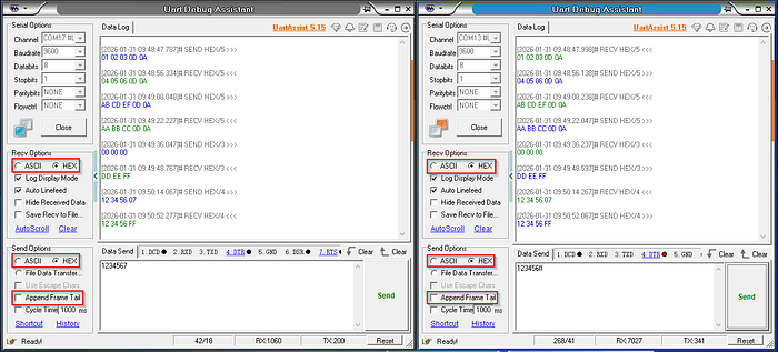
You will notice that the first four entries are ending with "0D 0A" because you enabled the option for "Append Frame Tail". When disabling this option, just the entered HEX data is transmitted.
Simple range test
For the sake of simplicity, I connected one module to an ESP32 device, simulating a responder of incoming messages. It will add an increasing number behind the received packet and transmit the data:
...
Received "A"
Responded "A003"
Received "A"
Responded "A004"
...
However, one disadvantage of these modules is that the signal strength of the incoming packet cannot be displayed or queried. For that reason, I set up the highest possible transmission power of +22 dBm for both devices and placed one device at the window of my living room on the second floor (around 6 meters above ground) and walked around with my laptop, typing messages and hoping for a response.
Later I placed the positive, working measurements (in both directions) in places on a Google map to measure the distance between the transmitter and receiver. As I'm living in a region with many buildings, in reality there is no line of sight after the next corner :-(
The maximum distance at which I could still receive and send packets was around 500 meters, with a multi-story, solidly built office building between the sender and my receiver. But I am very sure that better antennas on the transmitting and receiving module can improve the range, as can placing the transmitter in a more open and higher location. To be fair, the promised "kilometers" will certainly not be achievable in a densely populated area, but the range should be sufficient for transmitting data from the garden shed or garage.
Summary
It is super easy to use these LoRa module types when you need a simple connection between two computers. However, if you intend to use these modules for LoRaWAN or Meshtastic, I'm afraid I have to disappoint you. This is partly because they cannot freely adjust the necessary frequencies.
Source code of the app
As this tutorial is on a manual workflow, there is no code available. But I'm providing a lot of material around these modules, e.g., the downloaded support package. Please keep in mind that my material may get outdated, so downloading it from an "official" source is always the best choice.
Please don't be confused that the repository name and the directory itself contain references to source code—I simply didn't want to upload the material twice :-)
You find the material in my GitHub repository.
Happy coding.