When setting up any Wi-Fi network, there is one important decision to make: choosing the right channel. Especially when using multiple Wi-Fi networks within a building, it is very important to use a channel that is used as little as possible in order to reduce interference and increase speed. Let us use an ESP32 Cheap Yellow Device ("CYD") as a basis for a Wi-Fi Analyzer.
I chose a CYD because it has a pre-assembled TFT display, but you can also use any other ESP32 microcontroller with a different TFT display. The setup is tested on 3 different sized CYD models:
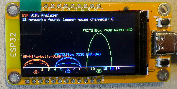
- a CYD with a 1.9-inches TFT display and a resolution of 170 x 320 pixels, driven by a ST7789 chip
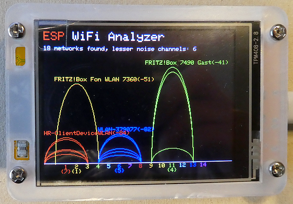
- a CYD with a 2.8-inches TFT display and a resolution of 240 x 320 pixels, driven by a ST7789 chip or an ILI9341 chip
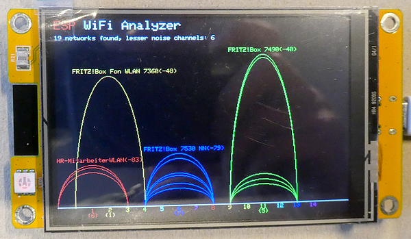
- a CYD with a 3.5-inches TFT display and a resolution of 320 x 480 pixels, driven by a ST7796 chip.
What are the topics of this tutorial?
- Additional websites about the CYD
- TFT Display driver library Arduino_GFX explained short
- Short explanation of the sketch
- Settings in the sketch to match the device
- Run the sketch and have fun
- Summary.
Additional websites about the CYD
- Developer website: the named devices have the "device numbers" "ESP32–1732S019" (1.9-inches display), "ESP32–2832S028R" (2.8-inches display) and "ESP32–3248S035", that were developed by a Chinese company. Their website is difficult to find, here is a link to the folder (containing all models). You will download a file up to 900 MB size!
- Probably the best website about the CYD is from a hobbyist, "witnessmenow" (Brian Lough), who maintains the GitHub repository "ESP32-Cheap-Yellow-Display" with a lot of FAQs and troubleshooting around CYD
- Another source for examples is "https://github.com/bitbank2/CYD_Projects"
- Sara and Rui Santos have a phantastic website around ESP32 topics, and they give a lot of information and examples, e.g. "Getting Started with ESP32 Cheap Yellow Display Board — CYD (ESP32–2432S028R)" and "ESP32 Cheap Yellow Display (CYD) Pinout (ESP32–2432S028R)". Use their search for more tutorials.
Arduino_GFX driver library explained short
Usually I'm using the TFT_eSPI or LovyanGFX libraries, but for this tutorial I'm using a different one: GFX Library for Arduino. It was developed by "moononournation" and I use the current version 1.6.3. The library is downloadable by the Arduino Library Manager.
This library is different to the TFT_eSPI library, as you define the settings for a display directly in the sketch, and you don't need to handle any user setting files.
To use the library, there are two main settings to main:
- select an Arduino_Databus
- select the driver for a display type
As the ESP32 CYD devices don't use the "native" SPI GPIOs for the display, we need to use an individual port mapping ("software SPI"). This is done by using "Arduino_SWSPI" for the databus, where the pin settings are done.
As our CYD models use three different display driver chips, we are using "Arduino_ST7789", "Arduino_ILI9341" and "Arduino_ST7796" for the display driver type.
Additionally, we define the "GFX_BL" setting to bring the display to light.
Btw: some displays need an additional activation of the electrical interface. This is done by uncommenting the "LCD_PWR_PIN" defining (not necessary for the CYD devices).
Short explanation of the sketch
This sketch is an example sketch from the library (examples ⇾ WiFiAnalyzer ⇾ ESPWiFiAnalyzer) ("ESPWiFiAnalyzer.ino").
Depending on your region, there are up to 14 Wi-Fi channels to select from, and the sketch is scanning each channel and detect the networks that are noticeable on the channel.
When all channels are checked, the collected data is displayed as elliptic curves. That is due to the fact that a Wi-Fi network that is e.g. operating on channel 3 also radiates (with less effect) onto the surrounding channels. Within the sketch, the painting is done by a "writeEllipseHelper" that is part of the library.
After a 3 seconds delay, the process is starting again.
Settings in the sketch to match the device
For an easy use, I defined four different settings for my own CYD variants, but you are free to define the settings for your own model. Simply uncomment, just one of the defining (in this case I'm using the 2.8-inches CYD with a ST7789 driver chip):
//#define CYD_1_9_INCHES_ST7789
#define CYD_2_8_INCHES_ST7789
//#define CYD_2_8_INCHES_ILI9341
//#define CYD_3_5_INCHES_ST7796
Run the sketch and have fun
I compile the sketch with the default settings for the "ESP32 Dev Module" (240 MHz, Partition scheme: default 4 MB with SPIFFS). After some seconds for the initial scanning, the results are plotted on the screen.
Summary
It is very useful to be able to use a small portable Wi-Fi scanner directly at the location where a Wi-Fi network is used. As the display is wired, you just need to upload the sketch, and you are ready to go.
Source code of the app
You find the complete code of the app in my GitHub repository.
Happy coding !