Overview
Many small microcontrollers lack a hardware UART, but serial communication projects remain possible. By using timers and interrupts, a fully functional software UART can be implemented, even on devices like the ATtiny85. In this article, we will design an efficient, non-blocking, and low-overhead software UART capable of reaching up to 19200 baud on an 8 MHz microcontroller using only a single hardware timer. Unlike many software UART implementations that rely on busy-wait loops, this design is fully interrupt-driven and requires CPU intervention only once per bit period.
What You'll Learn
By the end of this article, you will understand:
- How asynchronous serial communication works at the bit level.
- How to implement a UART entirely in software.
- How to use AVR timers in CTC mode for precise timing.
- How interrupt routines enable non-blocking communication.
- How to design efficient circular buffers.
- How to test the implementation using a microcontroller simulator.
If you enjoyed this, leave a clap or comment to support future articles.
Introduction
Serial Communication with UART
UART (Universal Asynchronous Receiver/Transmitter) is one of the most widely used serial communication methods in embedded systems, microcontrollers, and electronic devices. It provides a simple and reliable way to exchange data between components. Unlike other protocols, UART is asynchronous, meaning it does not require a shared clock signal between devices. Instead, both ends only need to agree in advance on a few parameters, such as the baud rate (transmission speed), number of data bits, parity configuration, and number of stop bits.
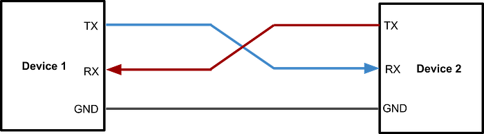
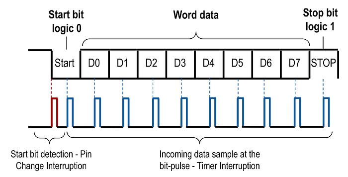
In a UART communication link, data is transmitted bit by bit through a TX (transmit) line and received through a separate RX (receive) line. Each byte is wrapped inside a frame that typically includes: one start bit, several data bits, and one or more stop bits. Because synchronization happens at the start of each frame, UART implementations can remain simple while still being robust.

Another important feature is that UART can operate in full-duplex mode, allowing simultaneous transmission and reception. In contrast, half-duplex mode only allows data to be transmitted or received at a time.
Due to its low hardware cost, ease of implementation, and broad compatibility, UART is commonly used for firmware debugging, communication with external modules (GPS, Bluetooth, sensors), bootloaders, and inter-microcontroller communication. Even when a microcontroller lacks a dedicated UART peripheral, it can still be implemented entirely in software using timers and interrupts — a technique commonly known as a Software UART or bit-banging.
The ATtiny85 Microcontroller
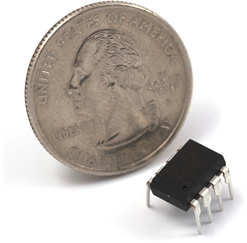
The ATtiny85 is an 8-bit microcontroller from Microchip's AVR family, designed for low-cost, low-power, and space-constrained embedded applications. Despite its tiny 8-pin package, it integrates several essential peripherals, including flash memory, SRAM, hardware timers, an Analog-to-Digital Converter (ADC), an analog comparator, and multiple power-saving modes. The ATtiny85 is especially popular in the maker community for minimalist designs where every pin matters.
Its RISC architecture allows most instructions to execute in a single clock cycle, providing solid performance even at relatively low clock frequencies. Because of its simplicity, versatility, and efficiency, the ATtiny85 is widely used in portable devices, automation systems, smart sensors, and low-power embedded projects.
Unlike many larger AVR microcontrollers, ATtiny devices do not include a hardware UART peripheral. Instead, they provide a USI (Universal Serial Interface), a flexible communication module that offers basic building blocks, including a shift register, timing control logic, and a bit counter. The USI can assist in implementing protocols such as SPI and I²C, and it can also be used as a building block for software UART implementations.
Project Goals
Implementing a UART using timers presents an interesting engineering challenge, as it requires precise timing control entirely in software. Although a UART could be implemented more easily with the USI module, this article focuses on building one using only a single hardware timer. This approach is particularly useful when:
- The USI is already in use.
- Multiple software UARTs are needed.
- Maximum control over timing is required.
The main challenges addressed in this implementation include:
- Achieving the highest possible communication speed on an 8 MHz microcontroller.
- Designing a flexible architecture that can easily support features like parity bits or different stop-bit configurations.
- Minimizing SRAM usage.
- Keeping the code compact and maintainable.
- Ensuring fully asynchronous, non-blocking operation.
- Supporting high-speed half-duplex communication and lower-speed full-duplex operation when needed.
UART Implementation
Choosing the GPIO Pins
For UART communication, we first need to define which pins will be used for transmission (TX) and reception (RX). On the ATtiny85, almost any available GPIO pin can be used for both functions, since this implementation does not rely on hardware peripherals that require fixed pin assignments. This flexibility is one of the key advantages of bit-banging: we are not tied to dedicated hardware pins.
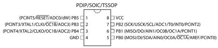
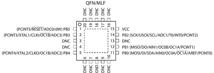
However, there are some considerations:
- If the USI module were used to implement a Software UART, the pins would need to be: PB0 → RX, PB1 → TX.
- If external interrupts were used instead of pin-change interrupts, PB2 would be required for RX.
- In our implementation, PB0 and PB1 were chosen simply for convenience, even though the USI module is not used in this case.
The first step is defining the corresponding pin masks. The following macros will allow us to indicate in the code which pins we will use.
#define UART0_RX_MASK (1 << PB0)
#define UART0_TX_MASK (1 << PB1)
The pin initialization is performed inside the uart0_init() function. For TX, the pin must be configured as an output and set HIGH, since the UART idle state is logic high. For RX, the pin must be configured as an input, and the internal pull-up resistor should be enabled to prevent floating states. The pull-up resistor prevents noise and floating input when no data is being transmitted. The configuration is done by setting the DDRB and PORTB registers.
To detect incoming data, pin-change interrupts must also be enabled on the RX pin. The GIMSK register enables this type of interrupt system, while the PCMSK register determines which specific pins can generate the interrupt. We do not use external interrupts (INT0), as this feature can only be used with a dedicated GPIO. If available, external interrupts can simplify the implementation. These interrupts let you choose whether the interrupts are triggered by a positive or negative edge, simplifying the code.
Finally, we must call sei() to enable global interrupts.
void uart0_init() {
    // Configure UART0_TX as output
    DDRB |= UART0_TX_MASK;
    PORTB |= UART0_TX_MASK; // Idle state is HIGH (UART idle)
    // Configure UART0_RX as input
    DDRB &= ~UART0_RX_MASK;
    PORTB |= UART0_RX_MASK; // Enable internal pull-up resistor
    // Enable pin change interrupt on RX pin
    GIMSK |= (1 << PCIE); // Enable pin change interrupt
    PCMSK |= UART0_RX_MASK; // Enable pin change interrupt for RX
    // Enable global interrupts
    sei();

    // ... Additional configuration will be added later!
}
Allocating a Reception Buffer
Since this UART implementation is interrupt-driven, the main program can continue executing while data is being received bit by bit in the background. Because of this, we need a temporary storage area to hold incoming bytes until the main program processes them. The most efficient solution in this scenario is a circular buffer.
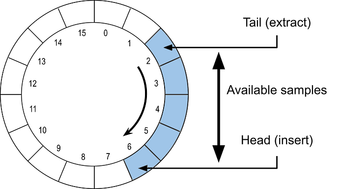
A circular buffer can be imagined as a ring of slots with two pointers:
- A head pointer indicating where new data is written.
- A tail pointer indicating where unread data begins.
This structure is simply an array of bytes, with values written sequentially. When the end of the buffer is reached, writing wraps around to the beginning — forming a continuous loop. In typical implementations, a buffer of size N can store up to N−1 bytes simultaneously.
The buffer size is defined by UART0_RX_BUFFER_SIZE. As we will see later, choosing a buffer size that is a power of two enables very efficient indexing via bit masking rather than costly module operations. Since the ATtiny85 has very limited SRAM, the buffer size must be carefully selected based on how quickly the main program consumes incoming data. In extreme cases, a buffer size of just 2 bytes may be sufficient.
#define UART0_RX_BUFFER_SIZE (8)

static uint8_t uart0_rx_buffer[UART0_RX_BUFFER_SIZE];
static volatile uint8_t uart0_rx_tail = 0;
static volatile uint8_t uart0_rx_head = 0;
Why is "volatile" needed?
The volatile keyword is essential in embedded programming when variables can be modified both inside and outside interrupt service routines. Without volatile, the compiler might optimize accesses by caching the variable in a CPU register instead of reading it from memory each time. This could cause the program to miss updates made by interrupts. Declaring a variable as volatile tells the compiler: "This value may change at any time — always read it from memory". It guarantees that the compiler does not optimize away memory accesses.
Configuring Timer0 as the Communication Clock
To generate precise timing for UART communication, we use Timer0, one of the two hardware timers available on the ATtiny85. Although Timer1 could also be used — or even both simultaneously for multiple software UARTs — Timer0 is sufficient for this implementation.
Before configuring Timer0, it is important to review some aspects of its operation:
- Each timer pulse increments a hardware counter. The value of this counter can be read or written at any time using the TCNT0 register.
- It is possible to configure a prescaler to reduce the frequency at which the counter increments. Since the ATtiny85 operates at 8 MHz, we will need lower UART frequencies. The prescaler is configured in the TCCR0B register, with available values of 1, 8, 64, 256, and 1024.
- There are two 8-bit (0–255) comparator registers, OCR0A and OCR0B, that generate interrupts when the TCNT0 counter matches their values. Each comparator can have a different value and trigger different interrupt routines. We will use this feature to separate the implementation of transmission and reception.
- There are several modes of operation for TIMER0, but in this case, we will use CTC mode (Clear Timer on Compare Match). In this mode, the TCNT0 counter is continuously compared with the OCR0A register. When both match, two events occur: an interrupt is generated, and the counter is automatically reset to zero.
- The second comparator (OCR0B) can only generate interrupts, but does not reset the counter when the match occurs.
Calculating Timer Values
Based on the desired frequency for the timer and the frequency of the microcontroller, the value of OCR0A can be calculated using:
OCR0A = f_clock / N_prescaler / f_timer — 1
or inversely:
f_timer = f_clock / [(OCR0A+1) * N_prescaler]
To apply these formulas, different prescaler values must be tested, starting with the lowest, until an OCR0A value of less than 256 is obtained. In general, it is recommended to use the smallest possible prescaler to minimize errors in the final frequency.
Example:
For 9600 baud UART communication with an ATtiny85 running at 8 MHz, a prescaler of 8 can be used. Therefore:
OCR0A = 8000000 / 8 / 9600–1 = 103.
When using this value, the actual frequency of the timer will be:
f_timer = 8000000 / [(103+1) * 8] = 9615,38Hz.
This results in an error of only 0.16%, well within the typical UART tolerance of 2%.
The following defines constants for values to achieve different UART serial communication speeds:
#define UART0_PRESCALER_2400 ((1 << CS01) | (1 << CS00)) // 64
#define UART0_TOP_VALUE_2400 (51) // 8000000 / 8 / 2400 - 1 = 51,0833
#define UART0_PRESCALER_4800 (1 << CS01) // 8
#define UART0_TOP_VALUE_4800 (207) // 8000000 / 8 / 4800 - 1 = 207,3333
#define UART0_PRESCALER_9600 (1 << CS01) // 8
#define UART0_TOP_VALUE_9600 (103) // 8000000 / 8 / 9600 - 1 = 103,1667
#define UART0_PRESCALER_14400 (1 << CS01) // 8
#define UART0_TOP_VALUE_14400 (68) // 8000000 / 8 / 14400 - 1 = 68,4444
#define UART0_PRESCALER_19200 (1 << CS01) // 8
#define UART0_TOP_VALUE_19200 (51) // 8000000 / 8 / 19200 - 1 = 51,0833
The initial configuration of the timer is performed within the uart0_init function, after configuring the pins:
void uart0_init() {
    ...
    TCCR0A = (1 << WGM01); // CTC mode, normal port operation
    TCCR0B = UART0_PRESCALER_9600;
    OCR0A = UART0_TOP_VALUE_9600;
}
Note that timer interrupts are not enabled yet. They will only be activated when data transmission or reception begins. While the UART is inactive, interrupts should remain disabled. If further power savings are desired, it would also be possible to completely turn off the timer; however, in this implementation, interrupts are disabled for simplicity.
Detecting the Start Bit
As mentioned above, the proposed implementation uses interrupt routines. During data reception, the microcontroller may be executing the main task while another device sends information.
ISR(PCINT0_vect) {
// Ignore rising edge
if (PINB & UART0_RX_MASK) return;
// Schedule first sample at half bit time
uint8_t tcnt = TCNT0;
OCR0B = (tcnt >=(UART0_TOP_VALUE_9600 >> 1)) ?
tcnt - (UART0_TOP_VALUE_9600 >> 1) :
tcnt + (UART0_TOP_VALUE_9600 >> 1);
// Enable RX sampling interrupt
TIFR |= (1 << OCF0B);
TIMSK |= (1 << OCIE0B);
// Disable pin change interrupt during reception
GIMSK &= ~(1 << PCIE);
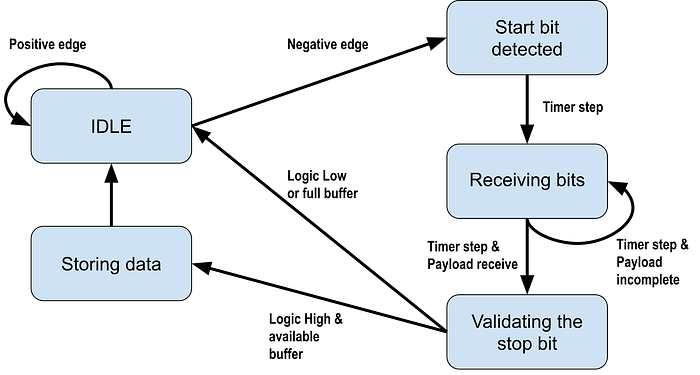
}First, the start bit is detected by interrupts caused by changes in the RX pin value. These interrupts are generated for both rising and falling edges, but UART reception should only begin on the falling edge of the start bit.
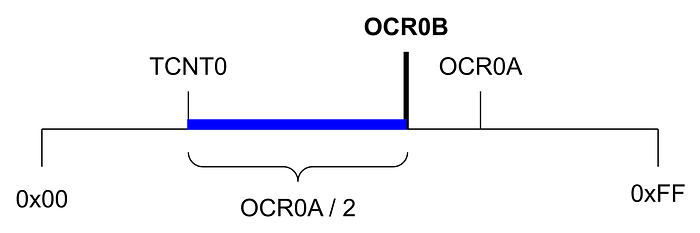
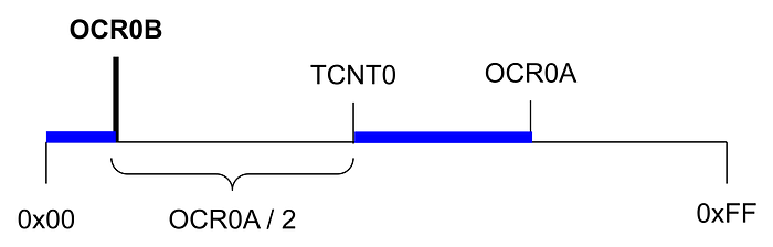
Once the start bit has been correctly detected, the timer is configured to generate interrupts at the appropriate times to sample the incoming bits. Since the start bit has just begun, it is necessary to position the first sample in the center of the bit to maximize tolerance for synchronization errors. In addition, sampling in the center of the bit reduces sensitivity to small differences in speed between the transmitter and receiver.
To achieve this goal, the value of the OCR0B comparison register is adjusted so that the first timer interrupt occurs half a bit-period later. Subsequent interrupts will occur automatically at the start of each full period, as determined by the value previously set in OCR0A. In practice, this is achieved by adding or subtracting half the timer period from the current value of the TCNT0 counter. The ">> 1" operator is an efficient way to divide by 2.
Next, pin-change interrupts are temporarily disabled to prevent new triggers that would interfere with the sampling process. Finally, timer interrupts are enabled. Before this, the corresponding interrupt flag is cleared to prevent any pending interrupt. Clearing flags before enabling interrupts is a good general practice in embedded systems.
Timer Sampling Interrupt (Compare Match B)
The interrupt routine associated with timer comparator B is used to implement UART data reception by periodically sampling the RX line. For each byte received, it is necessary to consider the start bit (low level) at the beginning and the stop bit (high level) at the end. Two static variables are used in this implementation: one to indicate how many bits remain to be received and another to store the byte being constructed. Since these variables are only used within the interrupt routine, it is not necessary to declare them as volatile. In the case of uart0_rx_bit_count, it is initialized with a value of 9 because the 8 data bits plus the start bit are counted.
static uint8_t uart0_rx_bit_count = 9;
static uint8_t uart0_rx_byte = 0;
The interrupt operation is simple. During the first nine samples (start bit plus eight data bits), the value read from the RX pin is shifted into the uart0_rx_byte variable. At each step, the content is shifted one bit to the right, and the new bit is inserted in the most significant position. The right shift allows the byte to be reconstructed in the correct order, since the UART transmits bits from the least significant bit first. Since a total of nine bits are processed, the first bit received (corresponding to the start bit) is automatically discarded at the end of the shifts.
Once the data bits have been read, the stop bit value is checked. If it is correct (high level), the received byte is stored in the circular receive buffer. The data is written to the position indicated by the uart0_rx_head pointer. If the buffer is full — that is, when the next index matches uart0_rx_tail — the received byte is discarded.
When the entire frame has been received, the timer interrupts are disabled, and the pin change interrupts are re-enabled to detect the next start bit. This way, the system is ready to receive the next byte.
// Samples incoming UART bits
ISR(TIMER0_COMPB_vect) {
    // Reading start bit + 8 data bits
    if (uart0_rx_bit_count){
        uart0_rx_byte = (PINB & UART0_RX_MASK) ?
            (uart0_rx_byte >> 1) | 0x80 :
            (uart0_rx_byte >> 1);
        uart0_rx_bit_count--;
        return;
    }
    // Stop bit validation
    if (PINB & UART0_RX_MASK){
        // Store byte if buffer not full
        uint8_t pos = uart0_rx_head;
        uint8_t next = (pos + 1) & (UART0_RX_BUFFER_SIZE - 1);
        if (next != uart0_rx_tail){
            uart0_rx_buffer[pos] = uart0_rx_byte;
            uart0_rx_head = next;
        }
    }
    // Prepare for next frame
    uart0_rx_bit_count = 9;
    // Re-enable start detection
    GIFR |= (1 << PCIF);
    GIMSK |= (1 << PCIE);
    // Disable sampling interrupt
    TIMSK &= ~(1 << OCIE0B);
}
It is important to note that the interrupt routine actually implements an implicit state machine, with the following states:
Reading Received Data
Data reading begins by checking whether any bytes are available in the receive buffer. To do this, the following function is implemented, which returns the number of bytes currently stored.
uint8_t uart0_available() {
    return (uart0_rx_head - uart0_rx_tail) & (UART0_RX_BUFFER_SIZE - 1);
}
It is important to note the use of the "&" operator and why the buffer size must be a power of two. This technique avoids using the modulo operator (%), which requires more CPU cycles. The operation works correctly even when the head pointer wraps around the buffer, as unsigned arithmetic maintains circular behavior. This technique, known as "circular masking," is very common in resource-constrained embedded systems.The following function retrieves data from the buffer. With each read, the uart0_rx_tail pointer advances one position, freeing up space in the circular buffer. A special value, INVALID_BYTE_VALUE, is used to indicate an empty buffer. In real applications, a value outside the protocol's valid range may be preferred.
#define INVALID_BYTE_VALUE (0xFF)

uint8_t uart0_read() {
    if (uart0_rx_tail == uart0_rx_head) return INVALID_BYTE_VALUE;
    uint8_t x = uart0_rx_buffer[uart0_rx_tail];
    uart0_rx_tail = (uart0_rx_tail + 1) & (UART0_RX_BUFFER_SIZE - 1);
    return x;
}
Transmitting Data
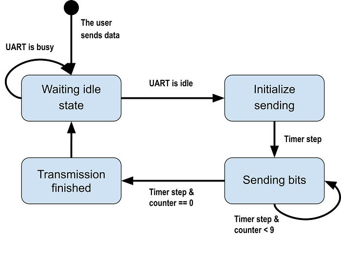
The transmission function is intentionally simple. Its only responsibilities are preparing the frame for transmission and starting the timer so that each bit is transmitted asynchronously within an interrupt routine. This design ensures the UART is non-blocking — once transmission begins, the CPU is free to continue executing other tasks.
Transmission requires two variables: a bit counter that tracks the number of bits remaining to be sent, and a variable that holds the full frame (start + data + stop bits).
// TX state machine variables
static volatile union {
    uint16_t u16;
    uint8_t u8[2];
} uart0_tx_data = {.u16 = 0}; // // holds full TX frame (start + data + stop bits)
A union is used here to minimize operations: it allows treating the frame as a single 16-bit value for shifting and reading and writing individual bytes for quick access. This technique reduces instruction count — an important optimization for small microcontrollers.
Before sending data, the UART must not already be in use. This is determined by checking whether timer interrupts are currently enabled. These macros inspect the TIMSK register to determine whether a transmission or reception is in progress, or both.
#define uart0_is_busy() (TIMSK & ((1 << OCIE0A) | (1 << OCIE0B)))
#define uart0_is_tx_busy() (TIMSK & (1 << OCIE0A))
#define uart0_is_rx_busy() (TIMSK & (1 << OCIE0B))
The function for sending data is shown below:
void uart0_send(uint8_t d){
// Wait while UART is busy
#ifdef UART0_FULL_DUPLEX
while(uart0_is_tx_busy());
#else
while(uart0_is_busy());
#endif
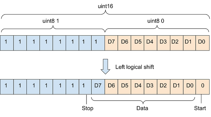
// Prepare frame: start + data + stop
uart0_tx_data.u8[0] = d;
uart0_tx_data.u8[1] = 0xFF;
uart0_tx_data.u16 <<= 1;
// Start transmission (enable timer interrupts)
TIFR |= (1 << OCF0A);
cli();
TIMSK |= (1 << OCIE0A);
sei();
}The first thing to do is to wait actively until the UART is free from a previous transmission. The while loop performs a busy wait that does not block interrupts, only stalling the main program flow. At this point, we must decide whether we want full-duplex or half-duplex communication. The behavior depends on how we implement the active wait (while loop):
- Half-duplex mode: Transmission waits until both TX and RX are idle. This is the safest mode for high baud rates.
- Full-duplex mode: Transmission waits until only TX is idle. Reception can occur simultaneously. However, full-duplex operation requires the CPU to service interrupts extremely quickly. At higher baud rates, interrupt latency may become a limiting factor.
It is important to note that full-duplex mode requires the microcontroller to execute interrupts quickly so as not to interfere with the others. Therefore, as will be seen later, full-duplex mode may have problems at very high transmission speeds.
Then, the frame is prepared for transmission using the union. The data to be transmitted is assigned to the least significant byte, while the other byte is only composed of bits set to 1 (stop bit). The entire integer is shifted one place to the left to generate the start bit. The following image illustrates how the bits are distributed within the integer variable.
Finally, the timer interrupts associated with the OCR0A comparison register are enabled, which starts the transmission process.
Why Use cli() and sei()?
Enabling the timer interrupt requires modifying the TIMSK register. This operation is not atomic — it involves a read-modify-write sequence. If an interrupt occurs between these steps and modifies the same register, it can cause inconsistent states or even a lockup. Wrapping the operation between cli and sei ensures the update happens safely.
Transmission Interrupt Routine
Actual bit transmission is handled inside the ISR(TIMER0_COMPA_vect). Each time the interrupt fires:
- The current bit is output on the TX pin.
- The frame is shifted right to prepare the next bit.
- The remaining bit counter is decremented.
- Once all bits have been transmitted, the variables are reset, and the timer interrupts are disabled, releasing the UART.
// TX state machine variables
static uint8_t uart0_tx_bit_count = 9;

ISR(TIMER0_COMPA_vect) {
     // Output current bit
    if (uart0_tx_data.u8[0] & 1)
        PORTB |= UART0_TX_MASK;
    else
        PORTB &= ~UART0_TX_MASK;
    // Shift to next bit
    if (uart0_tx_bit_count){
        uart0_tx_data.u16 >>= 1;
        uart0_tx_bit_count--;
        return;
    }
    // Transmission finished
    uart0_tx_bit_count = 9;
    TIMSK &= ~(1 << OCIE0A);
}
The counter starts at 9 because it includes the start bit and 8 data bits. The process ends with the stop bit and is not counted as a result.
Internally, the transmission logic also behaves like a small, implicit state machine, advancing automatically with each interrupt.
A key characteristic of this implementation is its efficiency: The CPU executes only a small amount of code once per bit.
Testing on a Simulation Environment
For initial validation, a simple test program was used. It continuously checks for incoming data and immediately sends it back over the UART. This is known as an echo test (or "ping-pong" test), a classic way to verify serial communication.
int main() {
    uart0_init(BAUD_RATE_9600);
    uint8_t b;
    while (1) {
        if (uart0_available()){
            b = uart0_read();
            uart0_send(b);
        }
    }
}
Notice that the main loop contains no delays or blocking operations, since all communication is interrupt-driven.
Testing was performed using SimulIDE v1.1.0-SR1 on Linux (https://simulide.com). This lightweight real-time simulator supports AVR, PIC, and Arduino devices. The setup consisted of an ATtiny85 microcontroller and a virtual serial terminal. This allowed sending arbitrary text and verifying that the echoed data was received correctly.
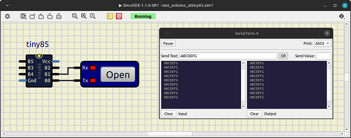
Once the simulation has started, the same message is transmitted continuously, with no delay between each one. In this way, we test our application under conditions where messages are constantly being received and must be processed quickly. In the simulator's serial terminal, we should see the same message that was sent previously. If some messages are missing or corrupted, it means the microcontroller cannot handle them fast enough, and the maximum reliable baud rate has been reached. The buffer size influences this test, so in my tests I used a size of 8 (suitable for small applications).
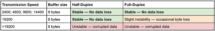
The limiting factor is interrupt latency: at higher baud rates, the CPU does not have enough time to reliably service overlapping RX and TX interrupts.
Conclusions
This project demonstrated a complete software UART implementation for the ATtiny85 using only a single timer and interrupt-driven bit-banging. The solution proved to be:
- Robust: Reliable up to 19200 baud in half-duplex mode.
- Lightweight: Only 540 bytes of flash (≈6%)
- Memory efficient: 16 bytes of SRAM usage
This leaves enough room to implement additional features — even a second software UART using the remaining timer.
Key Takeaway
Even highly resource-constrained microcontrollers can implement efficient communication peripherals when timers and interrupts are used carefully. However, this technique relies heavily on precise timing and interrupt responsiveness, making it less suitable for systems with strict real-time workloads. This demonstrates that even an 8-pin microcontroller can implement reliable serial communication without dedicated hardware.
Source Code
The complete implementation is available on GitHub:
https://github.com/victoradrianjimenez/attiny_uart/blob/master/uart_timer0/uart_timer0.ino