
PROJECT
Sometimes you create something just because … well, just because. This is a project that grew out of curiosity. A practical application still elludes me, so think of this as my lab notebook as I explore the world of infrared remotes. With any luck you can learn from my mistakes, or at least enjoy the ride.
Too remote
According to extensive research that I just made up, every household in Europe and North America contains an average of 7.3 infrared remote controls. The .3 is the remote you've kept for years in case you remember what it's for.
There are so-called 'universal' remotes that help you bring some semblance of order to this chaos. But I looked at the collection of devices in my home and thought, surely it would be an interesting project to replace them with Internet of Things (IoT) devices that could become part of my home automation obsession.
And so that's how I started down this particular rabbit hole. Where I ended up is debatable, but I have some working versions of the project that are sufficiently capable for me to declare 'mission accomplished'.
But as with so many hobby projects, I decided to push it a bit further, beyond my comfort zone and into areas new to me. And those versions don't work. I'm putting them aside for now, labelled as UFOs. (My wife is a skilled sewist and, apparently, incomplete projects in that domain are known as UnFinished Objects, a term every hobby should adopt.)
A basic design
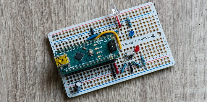
As I mentioned, the genesis of this project was simple curiosity. I wanted to know a little more about how infrared (IR) remote controls work. And so I threw together a project to read and generate the signals.
There are four components to this: an IR sensor to read signals; an IR LED to transmit them; a microcontroller; and a software library to do all the heavy lifting in the code.
That software library is IRremote for the Arduino ecosystem, originated by the legendary Ken Shirriff and actively maintained by a whole group of fine and dedicated people.
To get going, my microcontroller of choice was an Arduino Nano, but any microcontroller supported by IRremote (which is a long list) would have done.
Reading and sending signals
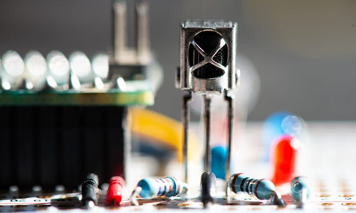
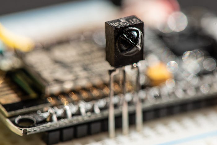
The sensors I'm using are marked VS1838B, although you'll find them referred to with other letters at the start, such as TL1838B. I'm not sure if there are significant differences. You can also find modules with the sensor and the supporting passive components in one handy package.
The 1838 devices work at 38KHz, which is a very common and popular frequency (most IR remotes operate somewhere in the 36–40KHz range). It contains a photodiode sensitive to a range of IR frequencies. Most IR remote controls operate within the near-infrared range, with wavelengths of around 850nm to 950nm. But they don't just flash data like Morse code. Instead, the sender emits a square wave signal — the carrier wave — at a particular frequency (38KHz in our case) and then it modulates that signal to form the data.
There are many ways of doing this. The NEC protocol is one of the most common methods you'll encounter and it sends a binary 0 by emitting the carrier signal for 562.5µs followed by a pause of the same length. To send a binary 1 it sends the same 562.5µs of carrier wave followed by a 1687.5µs pause.
The sensor I used is cheap and readily available. If you shop around, a few dollars will buy you a fistful of them, although if you prefer dealing with respectable vendors such as Mouser rather than random characters on eBay you could end up spending as much as a euro per sensor.
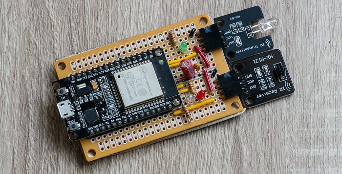
Wiring it up requires just a few passive components.
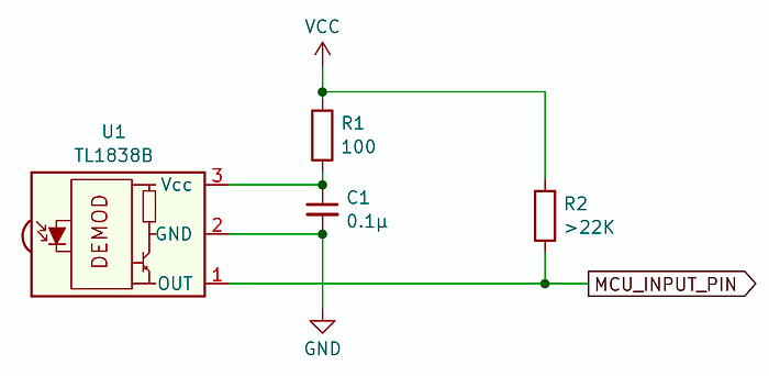
The datasheets I've found for the sensor have all tended to be somewhat sketchy, but the circuit I show above seems to work pretty well.
The datasheet seems to insist on a 100Ω resistor between the sensor and the positive power supply (3.3V and 5V supplies both work fine) and I have no reason to argue. It also wants a decoupling capacitor between positive and ground. The datasheet I have actually suggests having two but shows the same value for both of them. I went with one.
Finally, the output signal is active low so you'll want a pullup resistor on that line. Again, the datasheet suggests something weak — at least 22KΩ.
The electronics for sending IR signals are even simpler — an IR LED and its customary power-limiting resistor connected to one of the microcontroller's GPIO pins. I used a 330Ω resistor. I can't give you the full specs on the LED as I bought a bag of them via eBay a couple of years ago and have no records of exactly what they are. But they work.
Testing it out
I won't give a blow-by-blow account of the whole program. The code is available on GitHub and there's little more to it than loading the library and using a couple of its functions.
However, here are some of the highlights:
#include <IRremote.hpp>

// Pin assignments
#define IR_SENSOR_PIN  2    // connects to the sensor
#define LED_IR_PIN     3    // connects to the IR transmit LED
#define USE_ACTIVE_LOW_OUTPUT_FOR_SEND_PIN

// ... stuff ...

void setup() {
  Serial.begin(115200);

  IrReceiver.begin(IR_SENSOR_PIN, ENABLE_LED_FEEDBACK); // Start the receiver
  IrSender.begin(LED_IR_PIN);                           //and the sender

  // ... other stuff ...
}

void loop() {

  // ----- RECEIVE IR SIGNALS -------------------------------------------------
  if (IrReceiver.decode()) {
    if (IrReceiver.decodedIRData.decodedRawData != 0) { // Ignore repeats
      flashLED(LED_RECV_PIN, 1);
      IrReceiver.printIRResultShort(&Serial); // Complete received data
      IrReceiver.printIRSendUsage(&Serial);   // Statement to send this signal
      // ... anything else you want to do with the info ...
    }
    IrReceiver.resume();
  }

  // ----- SEND IR SIGNAL -----------------------------------------------------
  // Serial.println("Sending signal");
  // IrSender.sendNEC(0x1, 0x0, 1);
  // delay(2000);

}
You don't have to set up the GPIO pins you're connecting to the sensor and transmitter LED as outputs or inputs because the library takes care of that.
In the main loop, I have two sections, one of which is commented out. That's because this code is intended to do two things — read and decode incoming IR signals; and send a specific IR signal at regular intervals — but not both at the same time. For one thing, the commented-out sending routine is blocking, which means you would miss a lot of incoming signals if you tried to do both jobs. This is an issue to which we'll return.
I designed the Arduino-based project to print out (via the serial interface) information on received signals. That way I can easily map which signal is sent by each button on a remote. Alternatively, I can have the code send out specific signals at regular intervals
It's a project for playing with signals, not doing anything useful. In fact, I completed this part of the project a few years ago, then set it aside as a UFO. It had partially satisfied my curiosity about IR signals, but had one big drawback as an IoT device. It was not connected to the network.
Joining the network
When I took up the project again I was determined this device would become a thing on the internet. Well, not the internet exactly, but my local network.
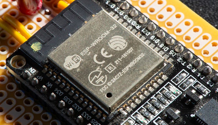
And the obvious solution was to replace the simple Arduino Nano with an ESP32 development board. I had a bunch of fairly generic and cheap development boards hanging around (branded 'DoIT').
I took the original code and added two key capabilities to it — wifi and MQTT.
Again, I turned to existing libraries to do the hard work.
#include <IRremote.hpp>
#include <WiFi.h>
#include <Adafruit_MQTT.h>
#include <Adafruit_MQTT_Client.h>
If you peruse the code on GitHub, you may also note a couple of other includes.
#include <MQTTconfig.h>
#include <WifiConfig.h>
This is my chosen method of handling private credentials so that they don't get uploaded accidentally to GitHub (there are other techniques).
The Arduino IDE keeps its libraries in a folder, not surprisingly called libraries, within your main sketchbook (project) folder. Inside libraries I have two folders — WifiConfig and MQTTconfig — that each contain a single header file — WifiConfig.h and MQTTconfig.h respectively.
The WifiConfig.h file looks something like this:
#define WIFI_SSID_MAIN "MyMainAP"
#define WIFI_SSID_ALT "MySecondAP"
#define WIFI_PASSWORD "SecretSquirrelPassword"
Yes, my house has two wifi access points (APs). If yours doesn't you can define just one. However, my wifi connection code is designed to switch from one to the other as it tries to establish a connection.
The MQTTconfig.h file doesn't contain anything sensitive, but it could if I started using authentication.
#define MQTT_BROKER "10.0.0.15"
#define MQTT_PORT 1883
The IP address is that of the server on my local network that is running the Mosquitto MQTT broker software. Port 1883 is standard.
So, by including these two files as headers I establish values I can use in any project without including them in the project repo.
Choice of message
The idea behind this hub is pretty simple. Programs on devices elsehwere on the network should be able to communicate with the hub to get it to emit IR signals that control other stuff. What other stuff? I'll get to that one day.
In addition, the hub needs to be able to read IR signals, decode them and send them out as messages on the network.
There are any number of ways you could do this. I considered HTTP-based REST APIs, for example. But in the end I settled on MQTT. It's a simple, well-supported protocol and doesn't require writing specific server code (well, not immediately, anyway).
All I needed to do was choose appropriate topics and a message format. I went with home/irrec as the topic used when the hub receives an IR signal and sends out an MQTT message — in other words, the hub publishes via this topic.
The hub subscribes to home/ircmd which is the topic used by other software to tell the hub what IR signal to send.
The format of the messages is:
<device_type>_<device_id>_<protocol>_<address>_<command>_<flags>

// EXAMPLE

IRHUB_10_8_0_68_0
The device type is strictly five characters and is IRHUB, IRSND or IRREC for reasons we'll get to later. For the ESP32-based hub I used IRHUB.
The remaining items are all 16-bit unsigned integers in decimal format. The first is a unique ID for this device. The others are all connected with the IR signal format.
I'm listening
The code as it currently exists on GitHub isn't what I started with, so a little explanation is in order.
First, we create some globals.
WiFiClient mqttWifiClient;

// --- MQTT CLIENT ------------------------------------------------------------
// Create an MQTT_Client class to connect to the MQTT server.
Adafruit_MQTT_Client mqtt(&mqttWifiClient, MQTT_BROKER, MQTT_PORT);
Adafruit_MQTT_Subscribe mqtt_sub = Adafruit_MQTT_Subscribe(&mqtt, SUB_TOPIC);
Adafruit_MQTT_Publish mqtt_pub = Adafruit_MQTT_Publish(&mqtt, PUB_TOPIC);
This is pretty much as suggested in the Adafruit documentation.
In the setup() function, we start serial comms and the IR receiver and sender as before. We also connect to the wifi (I use a function but this process is well documented and I don't do anything innovative or clever) and get our MQTT subscription started:
mqtt.subscribe(&mqtt_sub);
mqtt_sub.setCallback(mqttSubCallback);
The microcontroller is now listening for messages on a given topic and, each time it receives one it will invoke the callback function, which I have cunningly named mqttSubCallback.
The callback function parses the message, flashes an LED and, if the contents of the message conform to the NEC protocol, sends the appropriate code out via the IR LED. In other words, I can have a program anywhere on the home network send out an MQTT message and my device will emit the right code to … well, do something.
Listen to me
The main action takes place in the main loop().
void loop() {
  MQTT_connect();

  checkIRdecode();

  mqtt.processPackets(200);

  if (!mqtt.ping()) {
    mqtt.disconnect();
  }
}
We call a function to make an MQTT connection. It might sound excessive doing this every time through the loop. In fact, if the MQTT connection already exists, the function does nothing. If the connection has been dropped for some reason, the function re-establishes it.
The checkIRdecode() function is very similar to what we had in the main loop of the simpler program above. It looks for a received signal and, if found, decodes it and uses the data to create and send an MQTT message.
The next line is a source of issues. The mqtt.processPackets(200) will pause for 200ms watching for incoming MQTT messages. As before, if a message is received, a callback function handles it.
Before we go on to the problem, let's complete the loop.
We send a ping to the MQTT broker and, if we don't get a reply, we disconnect. Sending the ping keeps the connection alive. Disconnecting if there's no answer ensures we reconnect the next time around the loop. This whole routine is unnecessary if this client is talking to the broker often enough, but it's a good safety measure.
Stop blocking me
Now to that problem. The fact that the loop is waiting for 200ms for MQTT messages means that it could miss incoming IR signals because that routine is blocking.
At the same time, the fact that it's waiting for only 200ms for MQTT messages, and might be busy processing incoming IR signals at times, means that it could miss incoming MQTT commands.
In practice, I haven't noticed much in the way of missed messages and signals — perhaps one or two occasionally. But the potential is certainly there.
Some of you are probably way ahead of me. "But for heaven's sake," you're thinking. "Most ESP32s have two cores. Why not multitask?"
Why not indeed. Again, we'll get to that.
Divide and conquer
My thinking originally went in a different direction. Do I really need each device to be able to both send and receive? And the definitive answer I came up with was, well, um, maybe not.
I can see a situation where I have one or more IR-controlled gizmos that I want to be able to manage programmatically through home automation software. So I just need a device that receives MQTT messages and sends IR signals.
Similarly, in any given room I might need just one device that can receive IR signals from a remote and send out MQTT messages — most likely to devices like the one I've just described.
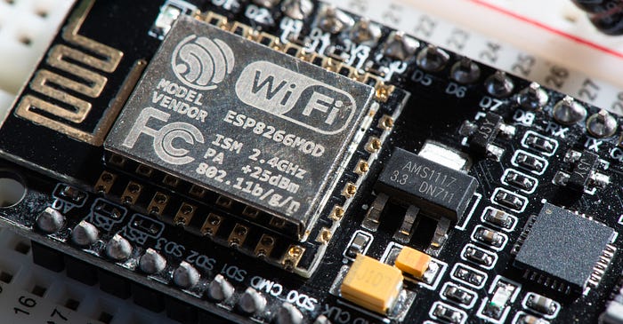
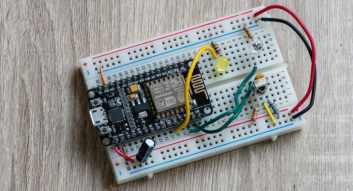
That led to two new versions of the device. Instead of the ESP32 I went with NodeMCU ESP8266 dev boards.
The code for them is pretty much the same, just trimmed for the specific functions. Their device names are IREC for the one that receives IR signals and sends out MQTT messages and IRCMD for the other. And the devices work a treat.
Multitasking
Yet that feeling that I should use the mutitasking capabilities wouldn't let go.
Let's recap. So far we have:
- A simple IR sender/receiver with no networking: WORKING.
- A single-tasking ESP32-based hub using MQTT and wifi. WORKING (mostly).
- Separate ESP8266-based sender and receiver devices. WORKING.
- Multitasking ESP32-based hub … umm…
I'm not going to delve too much into the code because clearly using FreeRTOS to multitask on the ESP32 is not my strong suit. In short, the code doesn't work.
I've tried two approaches. The first was to create a separate program for the multitasking version. This isn't in the repo because I realised I was creating two separate code bases for the ESP32 and that was silly.
So I went back to the main ESP32 code and included code for both single-tasking and multitasking versions. Which version is compiled depends on whether USE_MULTITASKING is defined.
When multitasking, the code for each core is put into its own function. I've called these processNetworkCommands() and processIRsignals(). And I can get either one of these working, but not both. It seems to depend on which core each is running on. This is something I need to delve into in much greater depth, but for now the multitasking version has achieved the status of UFO.
Far enough
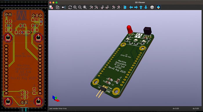
I have designed PCBs for the ESP32 and ESP8266 devices. In the case of the latter, the PCB can be made up as either a sender or receiver, depending on which components you attach. If I manage to save up a few pennies, I might get these boards fabbed.
I think I'll probably end up using the ESP8266 devices mostly. If I can work out what to do with them (answers on a postcard, please).
That multitasking business has me intrigued, though. It's time to learn more about FreeRTOS.
All the code for this project is available in my GitHub repository.
If you want a deeper dive into any aspects of the code, let me know.
Steve Mansfield-Devine is a freelance writer, tech journalist and photographer. You can find photography portfolio at Zolachrome, buy his books and e-books, or follow him on Bluesky or Mastodon.
You can also buy Steve a coffee. He'd like that.
My Friend retro games NES SEGA