RETROCOMPUTING
It might seem obvious, but the first thing you need to decide when designing and building a home brew computer is … what's going to be in it?
The answer is simultaneously simple and very complex. There are certain essential components without which it isn't a computer. These include a CPU, some form of input, some form of output and, ideally, a way to store stuff like programs and data.
With less than a handful of chips you can put together what you might call a 'minimally viable computer'. For example, with a CPU chip hooked up to a bunch of LEDs (that's the output) and a smattering of wires setting certain CPUs pins to high or low voltages (that's the input), you might get the 'computer' to run — ie, execute a small set of very simple instructions. But it's not going to do much and if you proudly present it to friends and family they'll start to worry about you.
You can build something around a microcontroller chip, such as the Atmel series made so popular by the Arduino platform. A microcontroller has all you need built into one chip — the CPU, storage (typically flash memory), RAM and I/O ports. But that's cheating.
When most people talk about homebrew computers, they mean something built around a microprocessor, the chip that does the computing but is going to need support from other components.
So, what's the least you'll need?
Memories
Computer programs execute within the computer's memory space. Typically, this consists of two types:
- Read-only memory (ROM), where the code (instructions and data) is permanently set in the chip. This is where you'll put most of the code that actually runs the computer which, if you're feeling ambitious, you can call the operating system.
- Random Access Memory (RAM), into which you can place code and information while the computer is running, replace it, modify it and delete it. But it all vanishes when you turn off the power.
There are other kinds of memory and in modern computers the picture is far more complex. And yes, I know a lot of you are going to think that this is kindergarten stuff that you already know, but the point I'm trying to make is that when homebrewing a computer you're going to have to think about every aspect. There are plenty of decisions to make around even these most fundamental of components. How much RAM? How much ROM and of what type? And how fast should it go?
And this is where I would advise that if, like me, you're embarking on your first homebrew machine, think small and slow.
Basic elements
Let's remind ourselves of the basic elements of the computer and then I'll walk through the decisions I made with the Zolatron project.
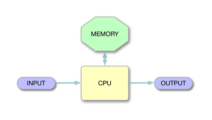
This is vaguely based on the classic von Neumann architecture.
The CPU
For me, the choice of CPU was easy. It had to be the venerable 6502, for reasons I explained in an earlier article. It's simple, has no exotic power needs, has readily available toolchains for developing software and it's available brand new.
It's also an 8-bit computer, meaning that the data bus, the collection of connections that bind components together so that they can exchange data, is only eight wires wide. That makes prototyping and designing circuit boards a lot easier than if you were dealing with, say, a 16-bit processor.
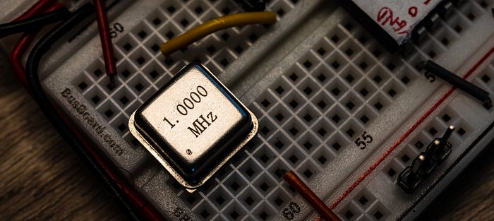
The 6502 actually performs reasonably well even at what most consider its lowest sensible clock speed of 1MHz. That's the speed I chose because I knew I would be starting on a breadboard, and even when I moved up to printed circuit boards (PCBs) they would be boards of my own design. Running at a modest clock speed means that the computer is far more tolerant of mistakes and poor design or component choices. That's why I suggest starting slow. You can always try cranking up the speed later, when you have at least some clue as to what you're doing.
And while on the subject of speed, you're also going to need a clock. A classic oscillator can will do the job nicely.
The memory
I decided my first computer would have 32KB of RAM. Even by the standards of the early 1980s (which was when my passion for computers first blossomed) that's not overly generous. On the other hand, when you're writing all your own code in assembly language, it's probably going to be far more than you need, especially for a first computer.
You could easily get by with, say, 16KB or even just 8KB of RAM. I plumped for 32KB because suitable static RAM chips are easily available and not expensive. And you can always choose not to use all the space. I went for the AS6C62256 static RAM (SRAM) chip. For a first machine, you probably don't want to mess with the complications introduced by dynamic RAM (DRAM), which constantly needs reminding of its contents. SRAM sits there remembering fine, so long as the power is switched on.
As for ROM, I went with 16KB. Again, you might get by with less, especially in the early stages. However, my ROM code — effectively the operating system of the Zolatron — has already grown to around 7KB. Partly, that's because I'm not a great programmer and so my code is not maximally efficient and compact. Having a 16KB ROM allows me to be a little sloppy.
During the development process, the ROM code is going to change frequently. You'll need to 'burn' the new version of the binary code to the chip. That's why most people use EEPROMs (electrically eraseable programmable ROM). With a handy chip programmer like the TL866 II Plus (which happens to be what I use), you can write the ROM code in a few seconds. I plumped for the popular AT28C256 EEPROM chip. This is actually a 32KB chip, but I use only half the space. I couldn't find a suitable 16KB device.
The 6502 has 64KB of 'address space' into which these chips map. With 32KB of RAM and 16KB of ROM, that leaves 16KB left over. But we haven't finished yet.
The I/O
The Zolatron uses memory mapped I/O. To write to or read from a device such as memory or an I/O peripheral, you send that data to or read from an address. We'll get into this much more in a forthcoming article when I will discuss address decoding. But for now, let's say that you've decided the serial port is at address B000. You want to send the character 'A' across the serial connection. So you load the hexadecimal value 41 (equivalent to the decimal value 65, which happens to be the ASCII code for the character 'A') into the Accumulator and then write the Accumulator to address B000. In assembly code, this looks something like this:
LDA #$41   ; load the value $41 into the Accumulator
STA $B000  ; store the contents of the Accumulator at address $B000
In 6502 assembly language, the $ prefix is used to denote hexadecimal characters.
This is a gross simplification — there's actually a lot more involved. The point I'm making is that you need to reserve some of the addresses in the 64KB space in order to talk to and hear from peripherals. Which addresses you use is up to you, but will be guided by how many peripherals you'll think you'll need. I originally allocated eight 'slots' in memory. Three of these were intially assigned to:
- A serial port, for the main input/output.
- A character-based LCD display, for additional output.
- A 'user' port, providing general-purpose I/O pins, much like on microcontrollers or single-board computers like the Raspberry Pi.
That left five spare slots for things I hadn't thought of. And there will be other things, so flexibility is a useful part of your design.
Those eight memory slots took up 8KB of the address map, which left a final 8KB unallocated. It's not uncommon — and certainly not a mistake — to have areas of the memory map free. I decided to mark this section 'For future expansion'. I would end up using it soon enough.
At this point, the memory map looked something like this:
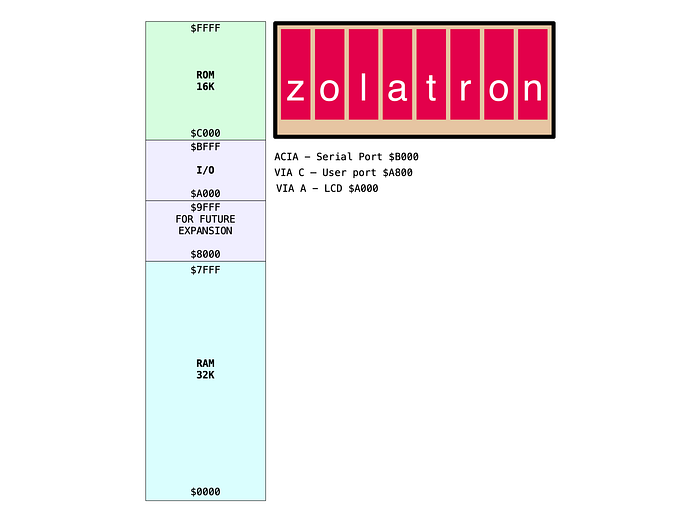
Certain elements — the ROM, RAM and the I/O space — would not change, although additional I/O elements would get added. Changing your mind later is not impossible, but does create a lot of work. And some aspects of this allocation were dictated by the hardware.
The 6502 chip uses the address space $0100–$01FF for the stack, where it temporarily stashes data. So there must be RAM at this location.
Similarly, it gets things going by looking at an address right at the top of the memory map ($FFFC). You have to make sure that $FFFC and its neighbouring $FFFD contain the two bytes that represent the address at which your operating system code starts. The 6502 reads this address, jumps to it and your code is running. The usual way of ensuring all this works as planned is to have a ROM sitting at those addresses with the relevant address coded into it.
What have we learned?
If any of this is confusing, don't worry. Explanations are on their way. However, I don't think I'm going to be able to get into every tiny detail of the code and the design.
This project was started a few years ago and is up and running in a more sophisticated form. If you want to jump ahead, you can go to the GitHub repo where you'll find code, documentation, schematics and even Gerber files for the PCBs.
And I strongly recommend Ben Eater's videos for a blow-by-blow account of getting a 6502-based computer up and running. As I mentioned in a previous article, the Zolatron quickly diverged from Ben's design, and bears little resemblance to it now, but all the principles are the same. Here's the first video to get you started.
In the next few Zolatron articles I'll be looking at address decoding and some basic interfacing.
You can find all the stories related to this project on the Zolatron feature page.
There is also a GitHub Zolatron repo with the code, datasheets and other documents.
Steve Mansfield-Devine is a freelance writer, tech journalist and photographer. You can find photography portfolio at Zolachrome, buy his books and e-books, or follow him on Bluesky or Mastodon.
You can also buy Steve a coffee. He'd like that.
My Friend retro games NES SEGA