ELECTRONICS
We humans respond strongly to sense memory. And while Proust had his recollections stirred by the taste of a madeleine, for many of us the variety of crude noises made by 1980s 8-bit computers is the gateway to nostalgia.
If there's one sound that makes me strangely wistful it's the brrrrr-BIP! of a BBC Micro being switched on. The 'Beeb' was an 8-bit microcomputer that played a critical part in the story of home computing in the UK of the early 1980s. It also helped get me hooked on computing.
In the 8-bit days, a computer succeeded or failed in part due to its sound capabilities, given that noises and music were so crucial to games. This was a strength, for example, of the Commodore 64, and to this day Commodore fans are known to wax poetic about the capabilities of the SID chip.
None of that much mattered to me. I was never a fan of computer games. And yet that start-up sound still pierces deep into my heart. It meant the start of an hour, or eight, at the computer, probing the mysteries of code and the online world.
And that sound — as well as pretty much all the Beeb's audio capabilities — can be traced to one chip — the Texas Instruments SN76489.
This chip was used in a whole host of devices, including Sega consoles and arcade games machines as well as home computers from Sord, Memotech and others. And so an entire generation grew up to the noises created by this chip.
Luckily, these chips are pretty easy to find on eBay. I couldn't make out a date code on the one I used for this experiment, but I assume it's old stock of some kind.
And it's also easy to use.
The ins and outs
The pinout is pretty simple. There's a pin for audio output which you need to feed to an amplifier. Most schematics suggest doing this via a capacitor which acts as a noise filter. I used a variety of capacitor values and couldn't detect that they had much of an effect.
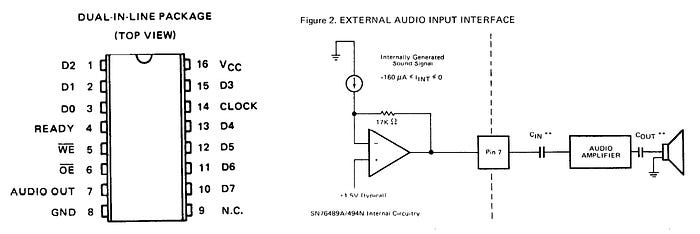
The datasheet suggests using a capacitor between the audio output pin and an amplifier, and another between the amp and a speaker. Your mileage may vary.
The main input consists of eight data pins (D0-D7) — essentially a byte-wide input bus. You write commands and data to the chip via these pins one byte at a time. In its infinite wisdom, TI decided that D0 should be the most significant bit and D7 the least. Whatever…
There's an active-low /OE (output enable, aka chip enable). I just tied this low, but you could put this under programmatic control if you want to.
The active-low /WE (write enable) pin is an input. Whatever you're using to control this chip — an Arduino in my case — pulses this low once data is set up on the eight data pins, and this tells the SN76489 that a byte of data is ready to be read.
You also need a clock input. In a computer like the BBC Micro this would be the main clock signal. For messing around with the chip, I used a 4MHz oscillator can. This matches the clock speed of the Beeb. On the version of the chip I have — the SN76489AN — this clock signal is divided by 16 inside the chip to create the internal clock. The maximum input clock speed is 4MHz. An 'N' version of the chip exists that divides internally by 2, has a maximum input clock frequency of 500kHz but requires only four clock pulses to load data compared to the AN's 32.
The chip has only one output pin other than the audio. The READY pin goes low while it's doing its stuff and then is set high again when the chip is able to accept more data. Theoretically, you could use this pin for flow control, but more often than not it was ignored.
Trying it out
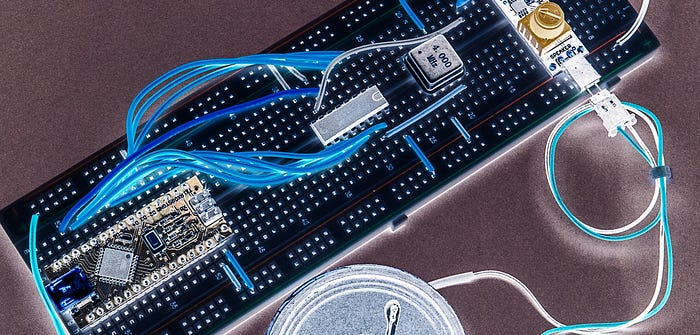
My test setup for playing with this chip was pretty simple. I used an Arduino Nano with eight GPIOs (D2-D9) connected to the data pins on the SN76489. D9 on the Arduino was connected to D0 on the sound chip because of the whole D0 being most significant thing.
I also connected D10 on the Arduino to the write enable (/WE) pin of the SN76489.
And like I mentioned, for a clock signal, I used a 4MHz oscillator.
The audio output pin of the SN76489 goes via a capacitor to the input of a tiny amplifier board that I had lying around. I imagine pretty much any amplifier might do for the purposes of playing around. Similarly, the speaker was a random device that was in my parts bin.
Driving the data
You could drive the eight data lines in a number of ways. On an 8-bit micro, for example, you might be tempted to feed these pins straight from the data bus. Alternatively, you could use a shift register.
On the BBC Micro (or, at least, the BBC Master I have) the lines are driven by port A of one of the 6522 Versatile Interface Adapter (VIA) chips. This port is also used for the keyboard and the MC146818 real-time clock chip. The /WE and /CE pins are commoned together and controlled via a 74LS259 addressable latch IC which itself is managed by four of the lines from port B of the same VIA chip. (The same four lines select other stuff, too.)
Writing to registers
Using the chip involves the familiar process of writing values to internal registers. The 74LS259 offers four channels — three (channels 0–2) make tones and the other (channel 3) is a noise generator.
Each of the four channels has a register that sets the tone/noise and another that sets the volume, making eight registers in all.
With the three tone channels, the tone register is 10 bits in size. This is obviously more than a byte, so we have to do some careful splitting up of this value to spread it across two bytes. We'll get to that soon.
With the noise channel (3) the register is three bits in size.
The volume registers for all four channels are four bits, giving values in the range 0–15. Actually, 'volume' is a slightly misleading term as the chip defaults to maximum volume and the value you feed it is an attenuation value, so that 0 is maximum volume and 15 is silent.
Basic process
The basic process with this chip is that you set up a byte on the eight data pins, then briefly pulse the /WE pin low to tell the chip that the byte is ready.
The byte you set up on the data pins is one of two types — a latch byte or a data byte. (To be pedantic, the latch byte also carries some data, but let's keep things simple.)
You use the latch byte to tell the chip that you want to write to a specific register (volume or tone/noise) for a specific channel. Once you've 'latched in' the register, all subsequent data bytes will be applied to that register until you send another latch byte.
For example, if you send a latch byte that specifies the volume register for channel 2, all subsequent data bytes will affect the volume of that channel.
So, how does the chip know if we're sending it a latch byte or a data byte? That's easy — the most significant bit (bit 7) tells it. If that bit is a 1, it's a latch byte. If it's zero, it's a data byte.
The meaning of the rest of the bits also depends on whether it's a latch byte or a data byte.
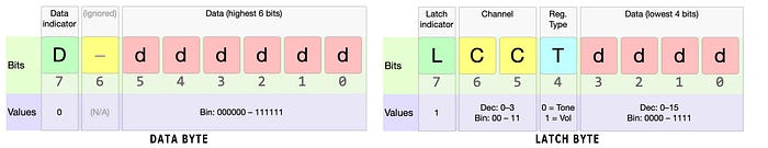
Latch byte
In the case of a latch byte, bits 5 & 6 are used to present a two-bit value (ie, decimal values 0–3) signifying which channel we wish to latch.
Bit 4 is used to tell the chip whether we wish to talk to the volume register (1) or tone register (0) for that channel.
The remaining four bits (0–3) are data and are put into the lowest four bits of the relevant register. When you talk to a volume register (which is 4-bit), this is all the data you need. But we'll talk in a minute about what happens if you subsequently send another data byte.
If you're talking to the noise register (ie, the tone/noise register of channel 3), four bits is too many, as it's a three-bit register. What happens is that the highest bit (bit 3) is simply ignored.
But what about the 10-bit tone registers for channels 0–2? The four lowest bits of the latch byte become the four lowest bits of the tone register, and this happens straight away. But that allows you to set values only in the range 0–15. If you want to set higher values — and you will — you need to follow the latch byte with a data byte.
Data byte
As I mentioned before, a data byte starts with the most significant bit (bit 7) set to 0. Bit 6 is ignored. The remaining 6 bits are transferred to whichever register is currently latched.
- If it's the noise register on channel 3, bits 3–5 are discarded and bits 0–2 set the register value.
- If it's a volume register, bits 4 & 5 are discarded, and bits 0–3 are used to set the volume register.
- If it's a tone register, all six bits are used, but they are shifted left four bits, becoming bits 4–9 of the register.
Setting the tone
Let's say you want to write the register value 0b1001110001 to the tone register of channel 2.
First you would send the value 0b11001001. Let's break down that binary number to see what's happening, starting from the most significant bit on the left:
1denotes this is a latch byte10specifies channel 20specifies a tone/noise register, not a volume register1001is transferred to the lowest four bits of the tone register.
At this point, you might expect the tone register to contain the value 0b0000001001, but that's a trap for young players. In fact, the upper six bits will contain whatever was last written to that register. But's let's assume, for the sake of argument, that those bits are, indeed, all zeroes.
Now we send the data byte 0b00100111. Again, let's break that down:
0denotes this is a data byte0this bit it ignored, but you have to set it to something, right?100111six bits to place into the register's bits 4–9.
The register will now contain the desired 0b1001110001.
Out loud
What about setting the volume?
We need to start by latching the volume register for the relevant channel. Let's go with channel 3 this time and we'll set it to volume level 0b0111 (7). We can send 0b11110111. Once again, let's break this down:
1denotes a latch byte11indicates we watch to latch channel 31says we want the volume latch0111is the volume we want to set
There's no need for a subsequent data byte as the latch byte contains all the data the chip needs (the same goes for setting the noise register on channel 3).
What if we were to sent another data byte straight after the previous one? Let's say we used 0b00101001. Here's what would happen to the bits (left to right again):
0denotes a data byte, so the chip knows it's getting more data0is ignored again10we'll be writing to a 4-bit register, so these bits are also ignored1001these bits are transferred to the volume register, setting volume level 9.
You can therefore keeping changing the volume as much as you like without having to send another latch byte. Similarly, if you set the noise latch for channel 3, you can keep altering the nature of the noise using just data bytes.
With tones, it's different. After latching in a tone register, subsequent data bytes will change only the top 6 bits — if you want to change the lowest 4 bits, you'll need to send another latch byte.
What's the frequency?
What do you get out? Let's look at tones first. The 10-bit value to set defines the 'half-period' of the resulting tone. That doesn't help much, does it? Fortunately, the datasheet provides a handy formula for determining the output frequency of the tone, which I've rewitten as:
f = Clk / ( 32 x reg)
Here, f is the tone frequency in Hertz, Clk is the frequency of your clock signal and reg is the 10-bit value you put in the register. Given that you are likely to want to know the register value for a given frequency (eg, musical note), we can re-arrange this as:
reg = Clk / (32 x f)
Making noise
The noise register on channel 3 is somewhat more complex, even though it uses only three bits. I'll be honest and admit I don't fully understand this, and the information here might be useful for people comfortable with terms such as 'linear feedback shift register'. But essentially, this is used to create white noise or various buzzes, burps and rumbles. The noise generator was heavily exploited for games (think, firing lasers or stuff blowing up).
Having fun
Part of the fun with playing with chips is simply trying things out and seeing what happens. That's what I did with the noise channel.
I started by trying to replicate the Beeb's start-up sound. Here's the most important section of the code.
delay(750);             // delay to enjoy default noise
setVolume(1, 15);
setTone(1, 0x90);       // vaguely BBC-like start-up beep
delay(200);
When the SN76489 is first powered up, it outputs a buzzy noise that BBC Micro owners will recognise as the first part of its two-tone startup sound.
In my code I placed a short delay to simulate the Beeb warming up, then played a brief tone. With a 4MHz clock, the output resembled that of the awakening Beeb.
Then it was time to go a little further. I wrote a program that plays an entire tune.
I've put the code on my Medium repo on GitHub. This is an attempted rendition of Daisy Bell. Some of you will know why I chose that. It seems to have the code for the Beeb start-up beep still in it, albeit commented out.
I'm not claiming this is optimised code — far from it. It's just what I hacked together to help me understand the chip. And while my efforts were somewhat crude, I gained an insight into the complex potential of this simple chip.
Steve Mansfield-Devine is a freelance writer and photographer. You can find photography portfolio at Zolachrome, buy his books and e-books, or follow him on Bluesky or Mastodon.
You can also buy Steve a coffee. He'd like that.
My Friend retro games NES SEGA