MICROCONTROLLERS
Electronic devices need to talk to each other. And I don't mean your smartphone app discussing groceries with your fridge. This is about one chip talking to another, or communicating with a sensor.
This is such a fundamental requirement that many techniques and protocols have been developed to facilitate this communication. I covered SPI on the AVR ATMEGA microcontrollers in previous articles. But there's another protocol, arguably more powerful, that is hugely popular and, if you understand it, opens up a world of potential devices — displays, sensors and much more — to use with your microcontroller.
In environments such as the Arduino IDE, much of the complexity of this protocol is taken care of for you, and it's remarkably easy to use. If you're coding in a bare bones AVR environment, however — which is what this series of articles is all about — you're going to need to do some more work. The reward is a better understanding of what's going on.
On the bus
Created by Philips Semiconductor, now NXP, the Inter-Integrated Circuit (I2C) protocol was designed to connect components, and particularly chips, that are in close proximity to each other. The name is typically pronounced eye-squared-see and is more properly written I²C, but I2C is easier to type.
This is the first of a group of articles looking at I2C on the AVR ATMEGA microcontrollers. But you can easily translate what we'll cover here to other platforms.
The bus isn't staggeringly fast, at a base standard of 100kHz. Faster versions are available — the 400kHz fastmode and even 1MHz, 3.4MHz and 5MHz options — but the original slow speed is still the most commonly used by tinkerers and hobbyists like me.
But it does have some advantages. The first is that the peripheral devices on the bus are addressable. Unlike SPI, where you need a separate line (and GPIO pin) for each device in order to activate it, with I2C you just preface traffic with the the device's address (a one-byte number) to select which device should respond. And it's also possible to have peripherals interact with multiple controllers, although that's beyond the scope of this current discussion.
In fact, I2C requires just two lines — a two-way data line (SDA) and a clock line (SCL) — which is why it is also known as the Two-Wire Interface (TWI), especially by manufacturers who don't want to pay NXP's licence fee. As we'll see, the AVR's registers and bits used to manage this bus mostly start with the letters 'TW'. So that's that mystery solved.
A bit complicated
There is a bit more complexity to using I2C compared to SPI. But once you get your head around a few concepts then it becomes much easier. One of the reasons I prefer using C++ to C is that you can write classes that hide much of the complexity. Yes, you can do this with functions too, but I like the 'black box' style of encapsulation of classes. All the wires are hidden.
I mention this because there's one bit of calculating you need to do with I2C — to set the bit rate for the clock — that is easy to mess up. Sticking it in a class method or function makes a lot of sense. So let's deal with that now.
By the way, I'm dealing here with microcontrollers such as the ATMEGA328P that have proper I2C interfaces and the registers to go with them. Some devices, like the ATTINY84A (another of my favourites), have an I2C mode, but via a Universal Serial Interface (USI) that is controlled in a different way, and will be none of our concern — for now, anyway. We'll get to it in the future.
Setting the bit rate
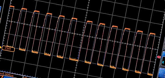
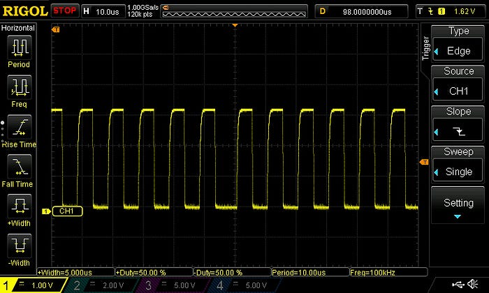
The controller device on an I2C bus is responsible for creating the clock pulses on the SCL line.
I'm going to assume we're dealing with devices that operate at either 100kHz or 400kHz. Achieving the bit rates necessary for the very fast I2C modes is beyond the capabilities of the ATMEGAs and ATTINYs I like to use.
You need to set the bit rate, which is the frequency of the SCL clock. It's set using the TWBR register and you calculate it using the formula:

That's how it appears in the datasheet. We can rewrite it as:
SCLfreq = F_CPU / (16 + (2 * TWBR * Prescaler) )
That still looks a bit ferocious, so let's break it down and also rearrange it, because the thing we're after (TWBR) is buried.
The SCLfreq is something we already know—it's the SCL clock frequency we want to use. F_CPU is also a known—it's the clock speed for your microcontroller. Let's rearrange this by multiplying both sides by (16 + (2 * TWBR * Prescaler) ) and dividing by SCLfreq:
16 + (2 * TWBR * Prescaler) = F_CPU / SCLfreq
We can also subtract 16 from both sides:
2 * TWBR * Prescaler = (F_CPU / SCLfreq) - 16
And now, to get the TWBR that we're after, divide both sides by (2 * Prescaler):
TWBR = ((F_CPU / SCLfreq) - 16) / (2 * Prescaler)
(You'll notice that I like to use lots of parentheses. I think it makes things clearer. If you prefer to rely on operator precedence, be my guest.)
In your code, you should have F_CPU defined somewhere anyway, so for an SCL frequency of 100kHz, the formula would be:
TWBR = ((F_CPU / 100000) - 16) / (2 * Prescaler)
If we assume, say, a microcontroller clock speed of 16MHz and a prescaler value of 1, this becomes:
TWBR = ((16000000 / 100000) - 16) / 2
Which is 72, which we'll need as an unsigned integer. In my I2C class I have an _init() method that, in part, looks like this:
void SMD_I2C_Device::_init(uint8_t address, unsigned long busSpeed)
{
    /* ... some stuff ... */
    uint8_t prescaler_options[] = {1, 4, 16, 64};
    uint8_t prescaler_value = prescaler_options[TWSR & 0b00000011]; // mask out status bits
    unsigned long baseFreq = F_CPU / busSpeed;
    TWBR = (uint8_t)((baseFreq - 16) / (2 * prescaler_value));
    /* ... other stuff .... */
}
We need to talk
Okay, so there's a couple of things that we need to talk about here. And the first is that prescaler.
The prescaler is defined in the two lowest bits (0 and 1) of the I2C status register, TWSR. These bits are known as TWPS1 and TWPS0. The values are set like this:
Bit 1    Bit 0    Prescaler
TWPS1    TWPS0    value
-----    -----    ---------
  0        0          1
  0        1          4
  1        0         16
  1        1         64
Here's the thing, though — I haven't yet worked out why anyone uses a prescaler value of anything but 1. In fact, Atmel recommends that you leave it at the default of 1 and set your bit rate purely by messing with TWBR.
If I had to guess, I'd say the prescaler is available for microcontrollers with very high clock speeds so that they can operate with devices with modest SCL speeds — ie, 100kHz — because then you'd need to get the value for TWBR down to something that can be stored in a single byte. But that's just a guess.
When using the ATMEGAs that I like, a prescaler value of 1 (ie, TWPS0 and TWPS1 both set to 0) is just fine and that's the power-up default.
So I could replace those two lines in the code above that determine prescaler_value by just having:
uint8_t prescaler_value = 1;
But I put those lines in on the off-chance that one day I might want to be able to set the prescaler value.
I could also probably do without the array and just have 4 raised to the power of (TWSR & 0b00000011). That involves including the math.h library.
uint8_t prescaler_value = pow(4,(TWSR & 0b00000011));
That's more concise, probably more efficient and almost completely opaque. Although it is the approach I tend to use now.
Maths problems
Doing a few sums, though, does show how you can run into issues if you're not careful.
Most of what I've done with I2C to date has been with an ATMEGA328P rolling along with an external oscillator giving a clock speed of a respectable 16MHz. But let's say you were using a microcontroller with an internal oscillator of 8MHz and a default clock division of 8, giving a 1MHz clock speed. So, let's try to control an I2C device at 400kHz from this chip. Plugging the numbers into the equation gives a TWBR of –6.75 (yes, that's a negative number). Oops! Somehow I don't think that's happening. So, under these circumstances, we're stuck with the 100kHz SCL speed.
Also be aware that Atmel advises that the CPU frequency of any peripheral device (should you be using, say, an ATTINY as a peripheral) should be at least 16 times higher than the SCL frequency.
In future articles, I'll look at how you actually starting communicating over I2C.
You can find all the AVR-related articles here.
I've created a GitHub repo for supporting files to accompany this AVR series of articles. You can find it here: https://github.com/mspeculatrix/AVR_8bit_Basics/
Steve Mansfield-Devine is a freelance writer and photographer. You can find photography portfolio at Zolachrome, buy his books and e-books, or follow him on Bluesky or Mastodon.
You can also buy Steve a coffee. He'd like that.