
ZOLATRON
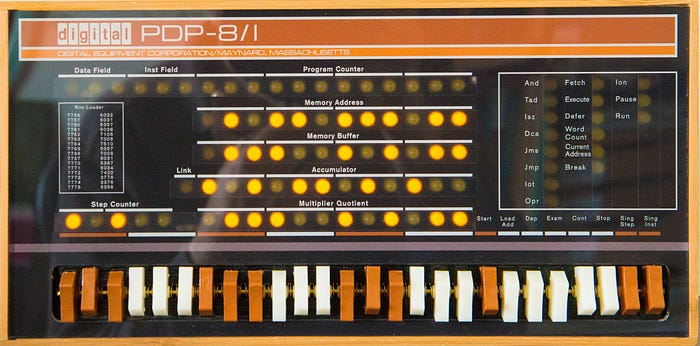
Bootstrapping computers used to be a slow and tedious business. A typical process might be something like this. After switching on and warming up the valves, you'd toggle in a small program using the rows of address and data switches on the front panel for each instruction or value. That might take a few minutes. It would be just enough code to allow the machine to read new software from a paper tape. That tape would contain just enough code to let you read more software from a stack of punch cards or a disk drive or … well, you get the picture.
Thank heavens we don't do that any more. Well, actually we do — we just don't know it.
Creature of habit
The 65C02 microprocessor that I'm using as the beating heart of my Zolatron homebrew computer requires something equivalent to that first bit of code that used to be switched in via the panel. Fortunately, the 65C02 is a creature of habit and when first powered on it always looks in the same place for that code. All we have to do is leave something for it to find— like baiting a trap — and we can kickstart the microprocessor and the whole computer.
On booting or on a reset, the 65C02 CPU looks for two bytes of data stored at addresses $FFFC and $FFFD. The contents of these two bytes are assumed to be the low byte and high byte respectively of a 16-bit address (low byte first because the 65C02 is little-endian, as are all the best CPUs), which together form the reset vector. A vector in this context is simply an address stored in a fixed location that tells the CPU where to go next. It's a way of saying: 'Thanks for asking, but what you're looking for is actually here.'
This is a process known as indirection. Why use it? Why not just have the CPU go to the final address to start with? The reason is flexibility. The location of the vector is fixed by the computer's architecture. So, like I said, the 65C02 always looks for the reset vector at the address $FFFC. But what it finds at that address is up to you, the designer/programmer of the computer.
Putting code in its place
In our case, what it's going to find is the start address of our system code. But how do we arrange that? How do we ensure that there are suitable values waiting for the CPU in these locations?
The almost-universal way of doing that is to have a read-only memory (ROM) chip, which contains permanent code that is available the moment you switch on the computer, occupying that part of the address map.
I've already talked about the address map for the Zolatron, and how we go about decoding addresses to allow the CPU to talk to various devices, such as memory.
Because the 65C02 defaults to those high addresses for important, immutable information, it's usual to have ROM code sitting in, say, the top 8KB or 16KB of the memory map. I opted for 16KB.
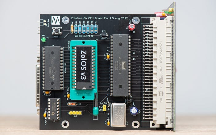
The ROM in the Zolatron contains all the code for what I like to call its 'operating system'. Whether it's worthy of being called an OS is debatable, but I've named it ZolOS nonetheless. It's the software that deals with the essential functioning of the machine, such as: reading from and writing to the serial port; file loading and saving; displaying text on the LCD panel; reading commands from the command line and responding to them; some maths routines; and much more.
This is code that is, more or less, required all the time and doesn't need to change depending on what task the machine is given. So having it in non-volatile ROM makes sense.
Being 16KB in size, my ROM starts at address $C000 and goes all the way to the top, $FFFF.
What I want the Zolatron to do, when switched on, is set the program counter register to the start of the ROM so that it starts executing code from there. And so I need to put the address $C000 into the reset vector. But before we look at how we do that, let's talk some more about ROMs.
Not really a ROM
The ROMs in many electronic devices, including the home computers of my youth, are 'mask' ROMs. The code enshrined in them is permanent and unalterable. The ROM is essentially a custom chip.
That's not a useful approach for the hobbyist, though. While you're developing the code to go in the ROM, you'll be making frequent changes and need to perform seemingly endless tests. It's not a 'one and done' proposition. Besides which, having mask ROMs manufactured is staggeringly expensive and only for serious enterprises.
So, instead, we typically use electrically erasable, programmable ROMs (EEPROMs) into which you can upload your code whenever you make a change. An EEPROM still has the benefits of a ROM, with the main one being that its contents are non-volatile.
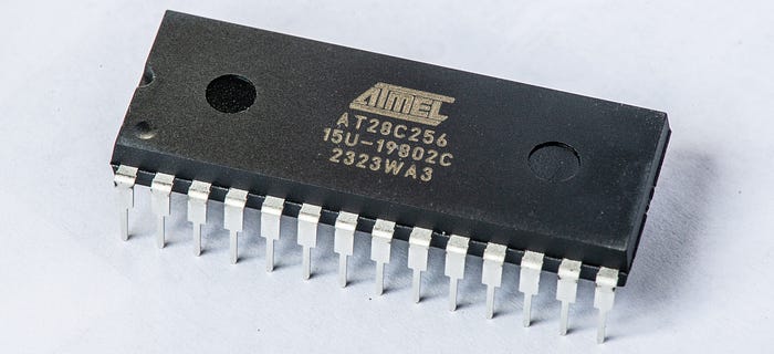
One quirk of the Zolatron is that the EEPROM chip I'm using — the Atmel AT28C256 — is actually a 32KB device. So I'm using only half the memory in the chip. And, in fact, I'm using the top half, because that's how it works out with the decoding logic. We'll see the consequences of that later.
Uploading the code
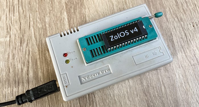
Naturally, you need a method of getting the code from your computer to the EEPROM. There are many ways of doing this, but here's my toolchain of choice.
I write the 65C02 assembly code in VS Code and assemble it using Beebasm. Then I burn the code to the chip with a TL866CS programmer, which is a USB hardware device. This is a very popular choice of programmer (although it may have been superseded now). It typically comes with a Windows program for reading and writing chips, but I've hardly ever used it. Instead, I prefer the open source Minipro command line tool by David Griffith.
I have a shell script that assembles the code and writes it to the EEPROM in one go.
#!/usr/bin/env zsh

CODE_VERSION="5.2.0"
WRITE_ROM=0

usage()
{
    echo "Error: Unknown option."
    echo "Usage: build [-w]"
    echo "    -w Write to EEPROM after building"
}

while [ "$1" != "" ]; do
    case $1 in
        -w )    WRITE_ROM=1
                ;;
        * )     usage
                exit 1
    esac
    shift
done

echo "Assembling z64-main.asm..."
OBJECT_FILE="bin/z64-ROM-${CODE_VERSION}.bin"

beebasm -v -i z64-main.asm -o ${OBJECT_FILE} -S VSTR=${CODE_VERSION} -d

# Get return code of last command
result=$?

if [ $result -eq 0 ]; then
    echo "- created binary file : bin/z64-ROM-${CODE_VERSION}.bin"
    if [ $WRITE_ROM -eq 1 ]; then
        echo "Writing to EEPROM..."
        minipro -u -p AT28C256 -w bin/z64-ROM-${CODE_VERSION}.bin
    fi
else
    echo "*** ERROR *** Code failed to assemble. Huh."
    echo "Exit code: $result"
    exit 1
fi

exit 0
Most of this is straightforward, I think. The one clever trick is courtesy of Beebasm, which allows you to insert variables at assembly time. The assembly code includes the line:
VSTR =? "0.0.0"When the code is assembled, I use the parameter:
-S VSTR=${CODE_VERSION}This inserts the shell script value CODE_VERSION into the assembly code variable VSTR. And then, in the ROM code I include:
equs VSTR, 0This embeds a null-terminated version string in a known location in the ROM code. But more on that in a moment.
ROM code
This is a highly reduced version of the ROM code for the Zolatron — at least, the first and last few lines.
ORG $8000
.startrom
ORG $C000
  jmp startcode
.version_str
  equs VSTR, 0
.startcode

  ; ... the main ROM code goes here ...

ORG $FFFA
.boot
  equw NMI_handler                          ; Vector for NMI
  equw startrom                             ; Reset vector
  equw IRQ_handler                          ; Vector for ISR

.endrom

SAVE startrom, endrom
Let's walk through this.
The opening ORG $8000 is a bit odd. The ORG directive basically says that the code starts at address $8000 and increments from there. You'll see there's a .startrom label immediately after this, so if we were to use the command jmp startrom, this would be taken to mean 'jump to address $8000'.
But then I immediately change the origin to $C000, which is actually where we want the ROM code to start.
This is all to do with the fact that the EEPROM I'm using is 32KB in size but I'm just using the top 16KB. Let's skip briefly to the end of the code where it says:
SAVE startrom, endromThis is a Beebasm instruction. It tells the assembler, when you build the code, start at the label .startrom and finish at the label .endrom. In our case, when the assembler comes to build the binary code, it will include a 16KB section from $8000 to $BFFF (which lies between the labels .startrom and .startcode) with no actual code in it!
It's all a bit wasteful (and a tiny bit time-consuming during the chip writing process) but it works.
After the ORG $C000 we then make an immediate jump to the label .startcode. This is simply to jump over the version string. From that point, we're off and running with the ROM code.
Then we get to the bit at the end. We set the origin with ORG $FFFA. The instruction equw is used to store a 16-bit value (least significant byte first) at the current address, and also increases the address by two bytes. NMI_handler is a label in the code at the start of the handler function for non-maskable interrupts. So the address of the NMI code gets stored at addresses $FFFA and $FFFB in the ROM.
Having done that, the current program address has now automatically incremented to $FFFC, which is where we need to put the reset vector. That's simply achieved using the label for the start of the ROM code:
equw startcodeYou could use equw $C000 at this point. But my method has the advantage that the reset vector actually doesn't point to the very beginning of the ROM, where it would simply encounter an instruction to jump past the version string, but to where the ROM code actually starts doing useful stuff. It doesn't matter how many characters are in the version string — the label automatically takes care of the actual address of .startcode.
To sum up, when the CPU starts up, it looks at the addresses $FFFC and $FFFD. What it finds there (in my code) are values something like 09 and C0 , presenting the address $C009 (.startrom plus the length of the version string plus the null terminator). It jumps to that address and executes whatever code it finds there.
Repetitive work
The experience of creating the ROMs can be somewhat tedious. With each change of the code that I need to test I have to:
- Switch off the machine.
- Remove the EEPROM chip. (Mine is in a quick-to-use ZIF socket for this purpose).
- Place the EEPROM in the programmer.
- Run the build script, waiting for the software to assemble and then get sent to the chip.
- Place the chip back in the machine.
- Switch on the machine and sigh, wondering why my code changes haven't fixed the bug or enabled the new function I was working on.
Other ways
There are alternatives. I've toyed with the option of a virtual ROM where a microcontroller emulates the ROM. The idea would be to have the build script simply copy the ROM code to the MCU over a serial connection. That's something I'm definitely going to toy with.
Another possibility is using flash memory, which is employed for the firmware of many modern devices. I'm in the process of building a prototyping or development board for flash chips.
And that's why I decided to create this basic introduction — as a background to future experiments.
I know a lot of this is going to be basic stuff for many people, but I wanted to cover it because it relates to certain other choices and approaches that I'll be dealing with later in the development of the Zolatron.
You can find all the stories related to this project on the Zolatron feature page.
There is also a GitHub Zolatron repo with the code, datasheets and other documents.
Steve Mansfield-Devine is a freelance writer, tech journalist and photographer. You can find photography portfolio at Zolachrome, buy his books and e-books, or follow him on Bluesky or Mastodon.
You can also buy Steve a coffee. He'd like that.