MICROCONTROLLERS
When you first start learning about coding for Arduino boards, most tutorials get you going by telling you how to set a GPIO pin high or low, usually to flash an LED. But when working with AVR microcontrollers directly, outside the Arduino ecosystem, there are more basic concepts you need to grasp before you start messing with pins — including registers, macro definitions and ports.
So much of what you do with an AVR is achieved via setting or reading register values. Essentially, these are locations in memory. Flip a bit or a whole byte in one of these locations and you control the behaviour of the chip. Conversely, reading what values have been set in these locations by other processes will tell you what's going on or allow you to read data from attached peripherals, sensors and the like.
Dealing with memory locations may sound scary, but the fact is you don't have to. Atmel has created a whole library of standard include files that use macros (ie, defines) to set up easily remembered names. When you install Atmel Studio (now Microchip Studio), for example, the standard libraries are included for you. They define a great many macros, and often there are alternate names for the same thing — you just use whichever suits you best.
In my article on setting up a dev environment, I touched on how your code needs to be able to read the standard AVR libraries. At the very least, you'll need to include the io.h header file. But one of the key functions this performs is to also include a specific header file for the particular microcontroller you're using. To ensure this is done, and you get the right header, your code needs to define a macro before including the io.h file. For the ATMEGA328P microcontroller, for instance, the start of my code always looks something like this:
#ifndef __AVR_ATmega328P__
#define __AVR_ATmega328P__
#endif

#include <avr/io.h>
I strongly recommend taking a look at the io.h file and seeing how it names the various microcontroller models.
Standard values
As well as the memory locations of registers, many standard values are given names via these macros. These can seem redundant — I mean, the following defines in portpins.h might seem a bit over the top.
/* Port Input Pins (generic) */
#define PIN7 7
#define PIN6 6
#define PIN5 5
#define PIN4 4
#define PIN3 3
#define PIN2 2
#define PIN1 1
#define PIN0 0
Using the macro PIN5 instead of the integer value 5 seems a tad pedantic, doesn't it? But it's not. The truth is your code becomes much more readable and understandable when you use these macros.
This isn't the only way to refer to a specific pin. You might want your code to show that you're referring to pin 5 on Port B. The Atmel macros have defined PB5 and PORTB5 for that purpose. When you look into the code you'll find that these are also defined as the integer 5 just like PIN5. So the following lines of code are, in fact, identical:
PORTB = PORTB | (1<<5);

PORTB = PORTB | (1<<PIN5);

PORTB = PORTB | (1<<PB5);

PORTB = PORTB | (1<<PORTB5);
That code sets pin 5 of Port B high, in case you're wondering. More on that later.
There is a potential trap here, though. These names make the code comprehensible but also mask the values we're dealing with. I said earlier that some macros are memory addresses — in fact, they're pointers to memory addresses. The PORTB we used in the example above is one such case. This has little significance in the simple line of code in this case. But it becomes important if you start doing things like passing port names as parameters to functions. We'll deal with that in a forthcoming AVR post.
Special names
Often, individual bits within a register will have their own names. You've seen one example with the names of the pins above. But let's look at something a little more sophisticated.
For the I2C (Two-Wire) interface there's a register called TWCR (two-wire interface control register). With the ATMEGA328P, seven of this register's eight bits are used to perform actions on the interface (the other bit is unused) and every one has its own name. For example, to read the I2C interface using acknowledge you need to set the 'interrupt' bit (bit 7, named TWINT, value 128), the 'enable' bit (bit 2, or TWEN, value 4) and the 'enable acknowledge' bit (bit6, aka TWEA, value 64).
Now you could do this by finding out the actual address of this register and writing the value 196 to it (128 + 64 + 4). But in six month's time when you re-read the code, you're going to be entirely baffled by that line. Instead, what you do is use:
TWCR = (1 << TWINT) | (1 << TWEN) | (1 << TWEA);Not only do you not have to remember (or look up) the values for anything, your code will also be a lot more portable should you refactor it for a different Atmel microcontroller. And the code is explicit about which bits are being set.
So the bottom line here is to read the Atmel documentation for your microcontroller to learn the names of all the registers and the values you set in them. Using these macro names ultimately makes life easier and your code simpler to maintain.
Flashing an LED
Like I said, pretty much the first thing anyone does with a microcontroller, whether it's a naked AVR chip or something fancy like an Arduino, is flash an LED.
Switching a GPIO pin high or low is a fundamental skill in microcontroller projects and it's made trivially easy in the Arduino environment thanks to much of the work being carried out by built-in software libraries. When you're working directly with AVR chips you have to put in a little more effort — but not much. And the additional steps make you think a little more about what's going on and help you to understand the architecture a little better.
And again this is about the cunning use of registers, which are the secret to doing anything with a microcontroller. Put crudely, you make things happen by writing a value to a register. You find out what's happening (eg, get input) by reading the values in registers. And a register is essentially just a location within the microcontroller's address space.
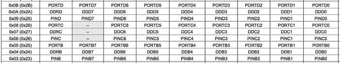
For example, the DDRB register on the ATMEGA 328, which controls whether certain GPIO pins are inputs or outputs, is a single byte at location 0x04. It's the Data Direction Register for port B. To set the pins as inputs or outputs, you simply write a value between 0 and 255 into that location. It would be a pain to have to remember (or constantly look up) that number, so the standard Atmel libraries define the macro DDRB that we can use wherever we want to make a reference to that register.
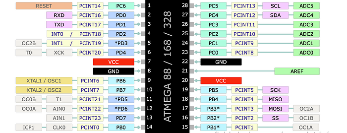
Ports and pins
Each AVR chip has a number of 'ports'. The Atmega 328 has three — 'B', 'C' and 'D'. (Want to know what happened to 'A'? Don't ask — it's never talked about…). Again, there's nothing very mysterious about ports — they are just a way of grouping together GPIO pins. Remember that we're dealing with an eight-bit architecture here. And in a moment we'll see that setting or reading pins requires writing to or reading from a register. As a register is one byte long, then the maximum number of pins it can handle is eight. So the pins are split up into groups of (at most) eight.
For each port there are three important registers:
- The Data Direction Register (DDRx) determines whether the pins operate as inputs or outputs.
- The port output register (PORTx) determines the actual value set on each pin when it's being used as an output.
- The port input register (PINx) is used for reading input values.
The 'x' in the abbreviations above is just my placeholder and varies according to which port we're discussing. So let's talk about Port B to show how this works. The Data Direction Register for Port B is labelled DDRB.
Data direction — In or Out
It's best to start thinking in binary when it comes to setting or reading values for registers because each bit within the byte at address DDRB represents a separate pin. To set a pin as an input you write a 0 to the relevant bit. To set it as an output you write a 1. So if you want all eight pins on Port B to be inputs you'd simply write 0 to DDRB (in binary,00000000). If you want them all to be outputs, you'd write 255 (in binary, 11111111).
Mixing inputs and outputs involves using intermediate values and you can quickly see why it's better to work in binary. For example, let's say you want the pins to be alternatively inputs and outputs, starting with pin 0 being an input, pin 1 an output and so on. The value you need to write to DDRB would be 170. Not obvious, is it? It's no clearer in hex: 0xAA. But in binary you can easily see what's happening: 10101010.
So to set the direction of the pins in C code you can simply write:
DDRB = 0b10101010; // using the '0b' prefix to denote binaryThat's fine if you want to set all the input/output configurations for all eight pins in one go. But that's not always the case. In fact, it's arguably more common to want to do one pin at a time.
Let's say you want to set pin 2 as an output. One way to do this is:
DDRB = 0b00000100;That's fairly clear, but it has a downside. At the same time as setting pin 2 as an output it also sets all the other pins as inputs — which may not be the effect you're after! Generally, it's good practice to focus purely on the pin in question and not risk side effects.
Luckily, there's a good way to do this. We use a logical OR. We take the existing state of DDRB and OR it with the new value. You could write this as:
DDRB = DDRB | 0b00000100;Those zeroes mean that the other pins will be unaffected and will stay in whatever state they're currently in. Pin 2 will be sure to be set as an output (regardless of its current state). A slightly more concise way of writing this is:
DDRB |= 0b00000100;But there's actually an even better way. As it stands, it's fairly clear what's going on here. But you still need to count the zeroes from the right-hand side to see which pin is being affected. And as it's in the third position, can you remember whether that's pin 2 or pin 3? (They actually count from 0.)
As we saw above, the AVR libraries define some handy macros for us. Instead of using numbers directly, we can use the label DDB2 to set pin 2 on DDRB. If you look at the definitions, you find that DDB2 is actually just the integer value 2 and using that in the line of code above wouldn't work. Instead, we use a 1 and 'shift' it into the appropriate position. The way you'd actually use this is:
DDRB |= (1 << DDB2);Now this probably looks more complex, not less. (Ignore the parentheses for a moment.) In fact, once you get used to it you'll find it's actually very natural and flexible. What we're saying here is take the value 1 (00000001) and shift it left 'DDB2' times. As DDB2 is just 2, then we shift left two times, resulting in the 00000100 we need.
Why do it this way? Well the 1 << part is always the same and you just get used to seeing it. You can understand it as meaning something like, "move a 1 into this position". In this case, you're moving a 1 into the position required to set DDB2 (ie, pin 2). Seen in that light it's clear and practically self-documenting.
And it's very flexible. Let's say we want to set pins 2 and 5 as outputs. All you need do is OR them together with the DDRB:
DDRB |= (1 << DDB2 | 1 << DDB5);Now you see why we put the parentheses in the first example — it makes it clearer what's going on.
What about going the other way — setting a bit to 0 to make the pin an input? We can use a similar approach. If we want to set pin 2 to an input, without affecting any of the other pins, we use:
DDRB &= ~(1 << DDB2);First we do the same as before, shifting a 1 into the position required to affect pin 2. This results in the familiar value of 00000100.
Then we use the bitwise NOT operator, represented by the tilde (~). This 'flips' all the bits, so we get: 11111011.
Finally we AND this with the Data Direction Register (rather than ORing). As the bit representing the pin we're trying to set is now a 0, this will guarantee a 0 following the AND operation, regardless of the original value. As all the other bits are 1s, then any bit that was already a 1 in the register will remain a 1. Any bit that was a 0 will remain a 0.
So this shows how you set up a port for input and output operations. In a forthcoming post we'll look at how you actually set or read the GPIO pins.
You can find all the AVR-related articles here.
I've created a GitHub repo for supporting files to accompany this AVR series of articles. You can find it here: https://github.com/mspeculatrix/AVR_8bit_Basics/
Steve Mansfield-Devine is a freelance writer and photographer. You can find photography portfolio at Zolachrome, buy his books and e-books, or follow him on Bluesky or Mastodon.
You can also buy Steve a coffee. He'd like that.
My Friend retro games NES SEGA